


7
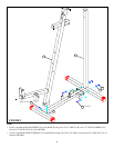
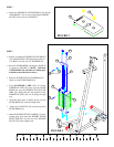
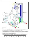
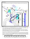
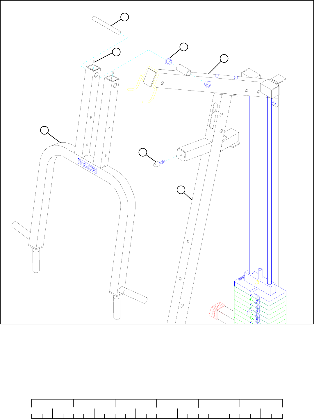
FIGURE 6
0
1
2
345
6
1/2 1/2 1/2 1/2 1/2 1/2
• Install two 5/16” SET SCREWS (50) into the top of the PRESS ARM (3) as shown in FIGURE 6.
• Insert two 3/4" FLANGE BEARINGS (29) into the TOP BOOM (7) as shown in FIGURE 6.
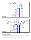
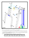
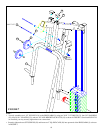
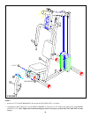
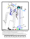
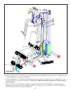
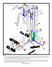
STEP 6
• Screw the ADJUSTABLE GLIDE (37) approximately 1/2” into the FRONT UPRIGHT (2) and tighten jam nut securely as shown.
• Attach the PRESS ARM (3) to the TOP BOOM (7) using the 3/4 X 7” SHAFT (13) as shown. Align the holes in the PRESS ARM
(3) with the 3/4” FLANGE BEARINGS (29) and tap the SHAFT (13) in place with a rubber mallet. The SHAFT (13) should be
flush with the outer edges of the PRESS ARM (3).
3
2
37
50
13
7
29