


11
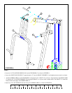
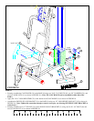
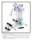
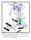
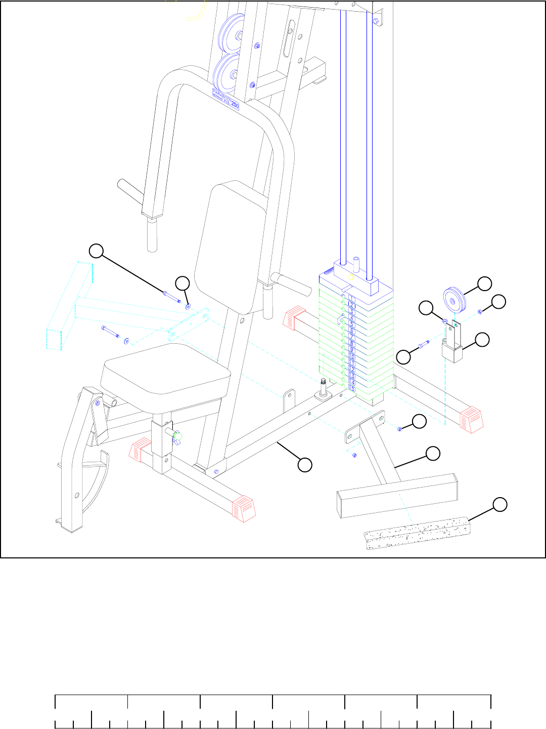
FIGURE 10
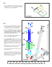
STEP 10
• Securely assemble the CALF BLOCK (10) to the BASE (8) using two 3/8 X 2-3/4” BOLTS (48), two 3/8” WASHERS (38), and
two 3/8” LOCK NUTS (41) as shown in FIGURE 10. (Note: The CALF BLOCK can be assembled to either side of the
BASE.)
• Apply the 4 X 14” NON-SKID STRIP (22) to the outside of the CALF BLOCK (10) as shown in FIGURE 10.
0
1
2
345
6
1/2 1/2 1/2 1/2 1/2 1/2
38
41
22
10
3/8 X 2-3/4” 48
8
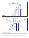
• Assemble the SWIVEL PULLEY BRACKET (5) to the BASE (8) using one 1/2” LOW HEIGHT LOCK NUT (42) as shown in
FIGURE 10. (Note: Tighten this connection enough to remove excess play yet al1owing SWIVEL PULLEY BRACKET to
rotate freely.)
• Securely assemble one 3-1/2” PULLEY (19) to the SWIVEL PULLEY BRACKET (5) using one 3/8 X 1-3/4” BOLT (49) and
one 3/8” LOCK NUT (41) as shown in FIGURE 10.
19
49 3/8 X
1-3/4”
41
29
42
LOW
HEIGHT