


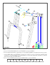
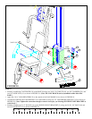
FIGURE 13
13
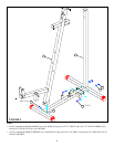
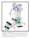
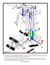
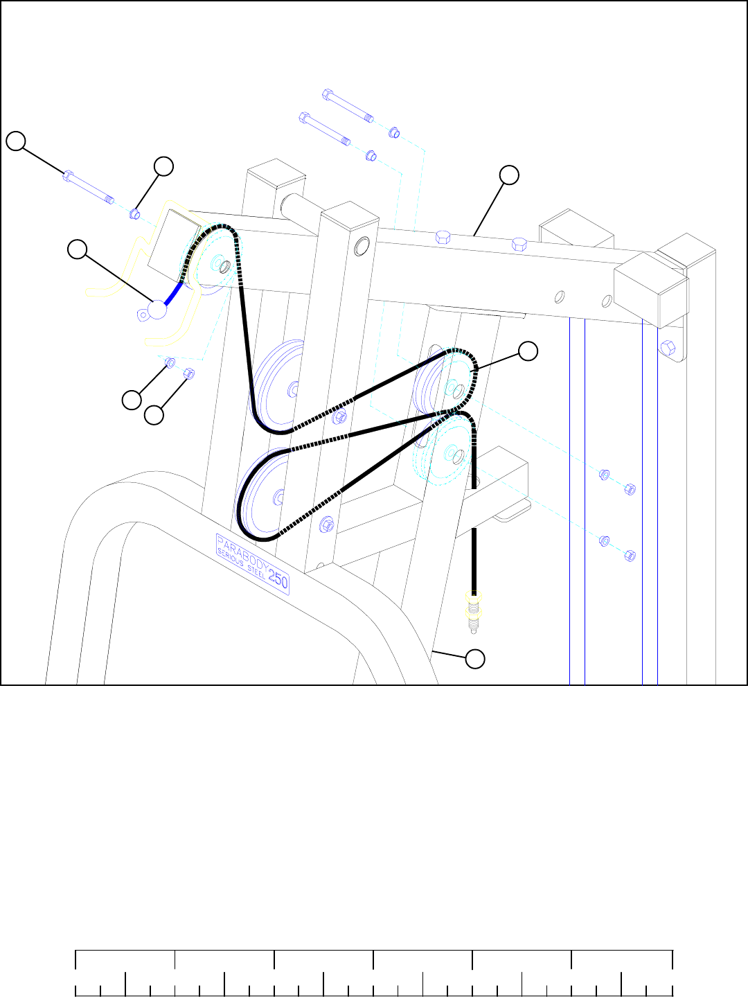
STEP 13
• Securely assemble the ball end of the WEIGHT STACK CABLE (26) and one 3-1/2” PULLEY (19) to the TOP BOOM (7) using
one 3/8 X 2-3/4” BOLT (48), two 3/8” FLANGE SPACERS (36), and one 3/8” LOCK NUT (41) as shown in FIGURE 13. (Note:
Loop the CABLE around the PULLEY prior to inserting it into the slot in the TOP BOOM.)
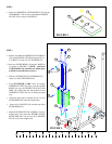
• Route the threaded end of the WEIGHT STACK CABLE (26) underneath the upper press arm pulley. Securely assemble the
WEIGHT STACK CABLE (26) and one 3-1/2” PULLEY (19) to the FRONT UPRIGHT (2) using one 3/8 X 2-3/4” BOLT (48),
two 3/8” FLANGE SPACERS (36), and one 3/8” LOCK NUT (41) as shown in FIGURE 13. (Note: Loop the CABLE around
the PULLEY prior to inserting it into the upper slot in the FRONT UPRIGHT.)
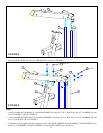
• Route threaded end of the WEIGHT STACK CABLE (26) around the lower press arm pulley, through the lower slot in the FRONT
UPRIGHT (2) , and down through the large hole in the FRONT UPRIGHT (2). Securely assemble the WEIGHT STACK CABLE
(26) and one 3-1/2” PULLEY (19) to the FRONT UPRIGHT (2) using one 3/8 X 2-3/4” BOLT (48), two 3/8” FLANGE SPACERS
(36), and one 3/8” LOCK NUT (41) as shown in FIGURE 13. (Note: Loop the CABLE around the PULLEY prior to inserting
it into the lower slot in the FRONT UPRIGHT.)
0
1
2
345
6
1/2 1/2 1/2 1/2 1/2 1/2
48 3/8 X 2-3/4”
36
19
7
26
36
41
* All connections use one 3/8 X 2-3/4” BOLT (48), two 3/8” FLANGE SPACERS (36), and one 3/8” LOCK NUT (41).
2