17
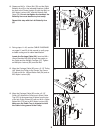
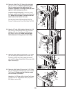
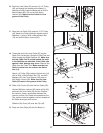
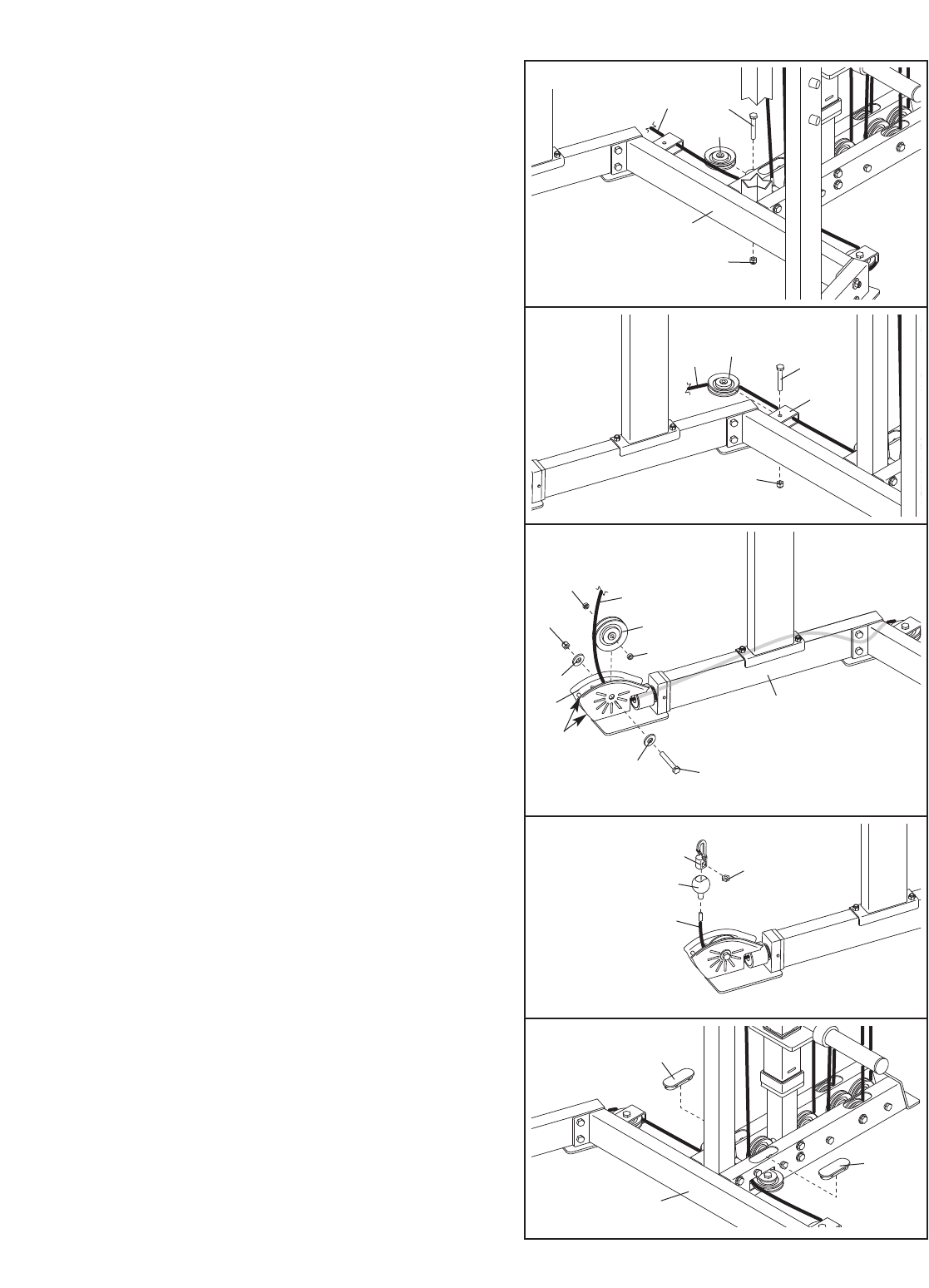
46. Route the Low Cable (55) around a 3 1/2” Pulley
(45) and through the bracket on the Base (1).
Attach the Pulley inside the Base with an M10 x
48mm Button Bolt (74) and an M10 Nylon
Locknut (62).
Make sure the Cable is in the
groove of the Pulley.
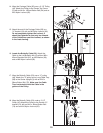
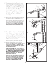
48. Thread the end of the Low Cable (55) into the
Cable Tool (not shown). Route the Cable Tool and
Cable through the Right Stabilizer (6). Make sure
that the Cable Tool is routed around the bolts
in the Stabilizer as indicated; if the Cable rubs
against a bolt, damage may occur. Remove the
Cable from the Cable Tool. Make sure the Low
Cable is routed over the rods on the Swivel
Arm (14).
Attach a 4” Pulley (89) inside the Swivel Arm (14)
with an M10 x 54mm Button Bolt (73), two M10
Washers (65), two 7mm Spacers (48), and an
M10 Nylon Locknut (62). Make sure the Low
Cable (55) rests in the groove of the Pulley.
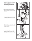
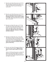
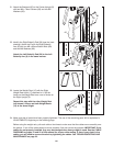
49. Slide a Clip Cover (43) onto the Low Cable (55).
Hold an M6 Nylon Locknut (63) inside a Clip (42),
and insert the Low Cable (55) into the Clip and
the Locknut. Insert a screwdriver between the
Locknut and the Clip. Rotate the screwdriver, the
Clip, and the Locknut together until two threads of
the Cable show past the Locknut.
Slide the Clip Cover (43) over the Clip (42).
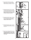
50. Press two Oval Caps (32) into the Base (1).
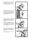
47. Wrap the Low Cable (55) around a 3 1/2” Pulley
(45). Attach the Pulley inside the bracket on the
Stabilizer (1) with an M10 x 48mm Button Bolt
(74) and an M10 Nylon Locknut (62).
46
47
62
62
45
55
1
1
62
74
45
55
48
49
50
73
62
48
48
55
89
65
63
42
43
55
65
Rods
14
6
32
32
1


