9
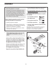
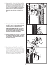
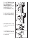
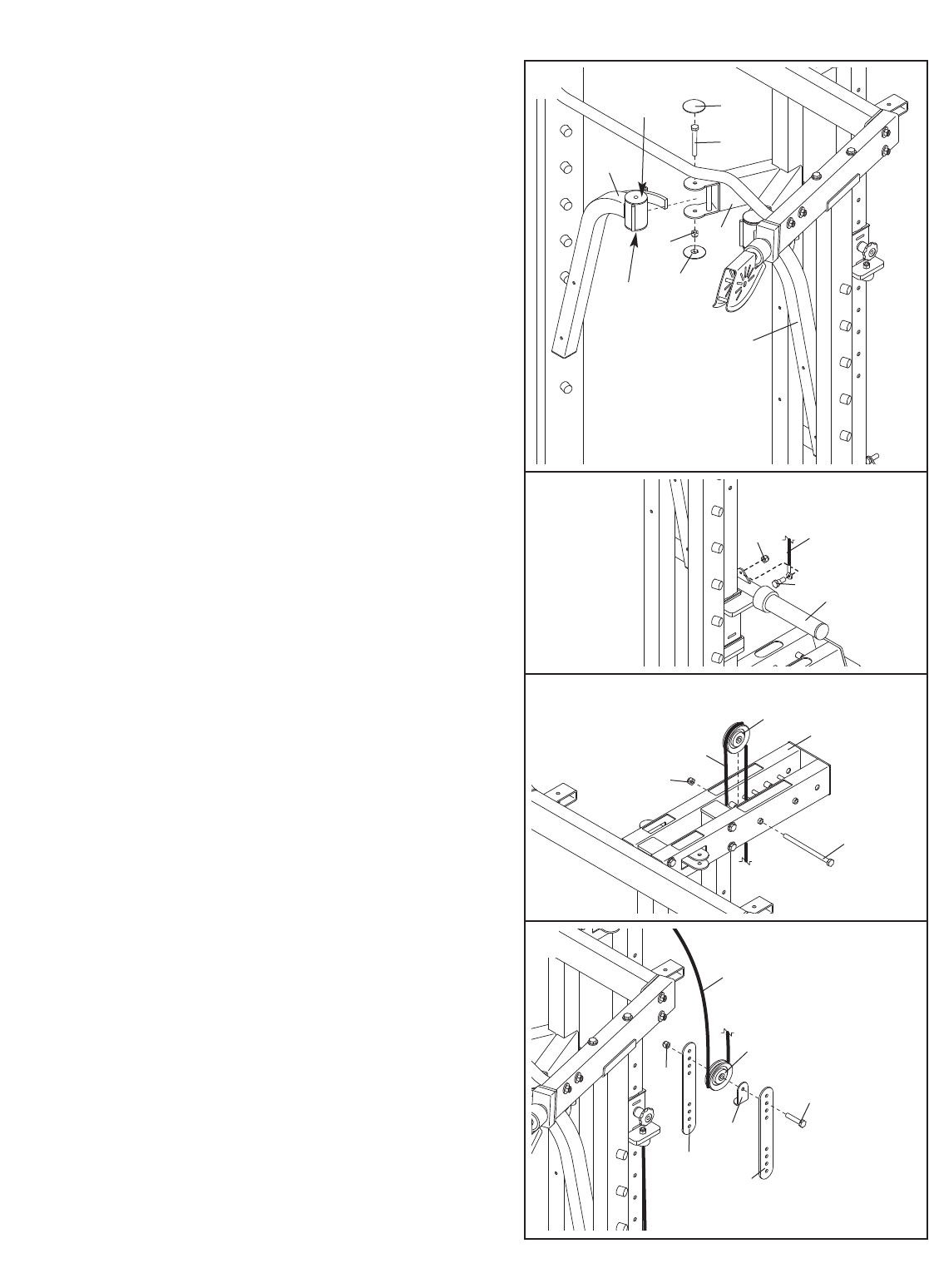
10. Grease an M10 x 112mm Bolt (76) and the Right
Butterfly Arm (8) in the indicated locations. Attach
the
Arm to the Center Upright (3) with the Bolt, an
M10 Nylon Locknut (62), and two Butterfly Bolt
Caps (52).
Do not overtighten the Locknut; the
Butterfly Arm must be able to pivot easily.
Repeat this step with the Left Butterfly Arm
(9).
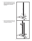
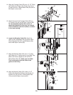
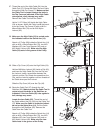
13.
Wrap the Carriage Cable (56) under a 3 1/2”
Pulley (45).
Attach the Pulley and a Short Cable
Trap (47) at the second set of holes from the top
of the two Pulley Plates (20) with an M10 x 54mm
Button Bolt (73) and an M10 Nylon Locknut (62).
Make sure the Cable T
rap is oriented to hold
the Cable in the groove of the Pulley.
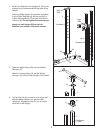
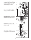
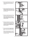
12. Wrap the Carriage Cable (56) over a 3 1/2” Pulley
(45). Attach the Pulley to the Center Top Frame
(2) with an M10 x 192mm Button Bolt (64) and an
M10 Nylon Locknut (62).
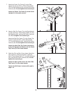
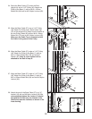
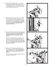
11. During steps 11–49, see the CABLE DIAGRAMS
on pages 21 and 22 of this manual to verify prop-
er cable routing and for cable identification.
Locate the Carriage Cable (56). Insert an M8 x
19mm Shoulder Bolt (80) through the eyelet on
the Cable and the Weight Carriage (12). Tighten
an M8 Nylon Locknut (82) onto the Bolt.
10
52
76
8
62
52
Grease
Grease
9
3
11
80
12
56
82
12
13
45
62
2
56
64
56
45
47
62
20
20
73


