


NVS 6
MANUAL
Page 17
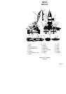
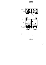
Carriages (6) and (7) can be moved upwards/downwards by
rotating adjustment screw (8), as well as left/right with the aid of screw (9)
to adjust the position of the night-vision goggles relative to the pilot’s eyes.
The adjustment is performed with the use of the screwdriver, part of the
single set of spare parts.
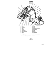
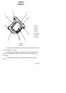
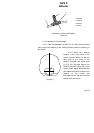
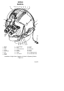
5.5.3 Casing (8), shown in Fig. 3.1, is intended for replacing the
helmet standard casing, which makes it possible to fasten the night-vision
goggles. Three holes provided at the casing center are used for installation
of mount (7) as shown in Fig. 5.1. After attaching the casing on the
external surface of the helmet front portion with four screws (16), it
protects visor guard (17) against any possible damage. Slots (18) are
used as guides when lowering and lifting the visor guard. They help to
hold the visor guard in the required position with the use of retainer cross-
shaped knob (19) moving along the slot of the casing, together with the
visor guard. While replacing the casing, the retainer cross-shaped knob
can be installed for using by the right or left hand of the pilot.
5.5.4 Clamp (9), shown in Fig. 3.1, is meant for fastening the visor
guard when replacing the standard casing for the casing found in the set
of spare parts. The clamp together with the visor guard fastened in it is
attached to the casing with the help of the retainer shown in Fig. 6.1.
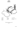
5.5.5 Counterweight (10), shown in Fig. 3.1, is intended to
compensate for the tilting momentum produced by the unit.
The counterweight is essentially an individual assembly consisting
of a canvas cover with a weight contained therein. As shown in Fig. 5.1,
counterweight (9) can be quickly installed on the rear portion of the helmet
through the use of the sticking fastener. The mass of the counterweight is
620 g.
The counter weight also has a strap with a sticking fastener used
for securing night-vision goggles power cable (15).