


NVS 6
MANUAL
Page 14
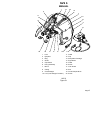
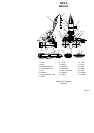
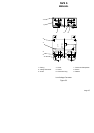
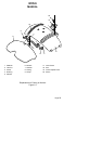
The design of the LVC is illustrated in Fig. 5.3. Structurally, the LVC
consists of casing (1), which accommodates voltage converter (2)
attached to it by means of screws (3). Cover (4) is fastened to the casing
with screws (5). Connector plug (6) serves to connect the LVC to the
helicopter electrical system of 27 V with the aid of the cable arranged on
board the aircraft.
Connector receptacle (7) is intended to connect cable (11), shown
in Fig. 5.1, to the LVC.
Connector plug (6) and connector receptacle (7) are secured to the
casing by means of screws (8) as shown in Fig. 5.3.
Gaskets (9) installed between the casing, the connector plug and
the receptacle serve to protect the LVC interior against direct entry of
moisture, whereas LVC cover (4) is filled with sealing compound for the
same purpose. Cable (11) attached to the voltage converter is connected
to cable (15) to make an electric power supply circuit of the night-vision
goggles as shown in Fig. 5.1.
The use of cables with quick-disconnect connectors makes it
possible to promptly remove the night-vision goggles from the helmet in
case of emergency.
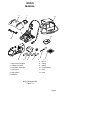
5.5 Apart from spare dehydrator cartridge, the single set of spare
parts includes the following: test pattern, mount, casing, clamp,
counterweight, screwdriver, cloth, spare batteries or rechargeable
batteries. Spare parts availability is optional, to be specified in each
individual supply contract.
5.5.1 Test pattern (5), shown in Fig. 3.1, is designed for checking
the quality of the image of the NVS 6 (resolving power). The check
procedure is presented in 6.2.21 of this Manual.
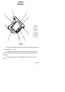
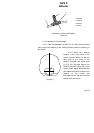
5.5.2 The mount, shown in Fig. 5.4, is intended to secure the
NVS 6 on the helmet of the pilot or a helmet of a similar type.