


14
MECHANICAL SERVICE GUIDE
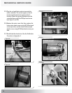
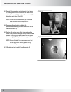
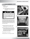
2-15 Plug the red and black motor wires onto the
motor controller. The red wire goes on the A+
terminal and the black wire goes to the A-
terminal. Attach the green ground wire to the
controller/frame with the Phillips head screw
(see Figure 7 and 7A).
2-16 Replace the motor cover first, then replace the
lower outer plastic cover using (4) Phillips head
screws per side, and the lower inside upright
plastic cover using (4) Phillips head screws, per
side.
2-17 Recalibrate the electronics. See the Calibration
Procedure in Appendix 4.
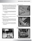
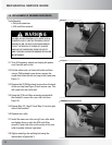
Figure 5:
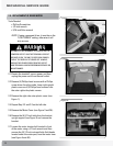
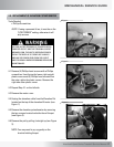
Figure 6:
Figure 6B:
Figure 5A:
Figure 6A: