17
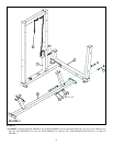
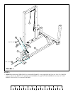
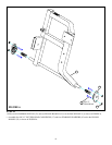
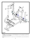
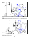
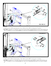
STEP 15:
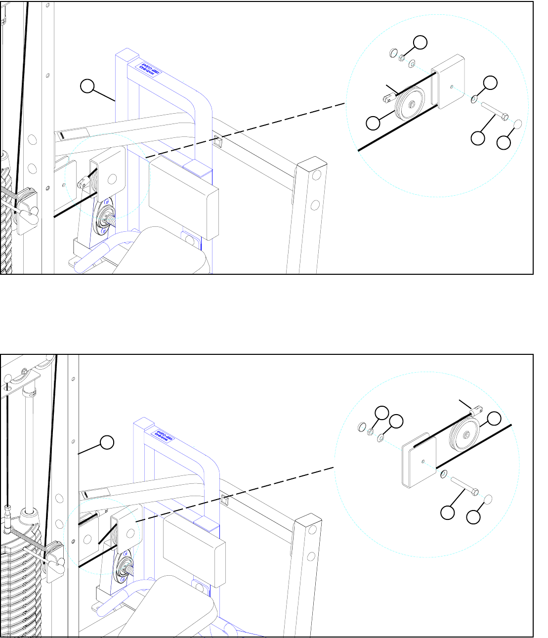
FIGURE 15
• SECURELY assemble the 4-1/2” PULLEY (39) to the vertical pulley bracket on the BACK PIVOT (5) using two RH CAPS (28), one
3/8 X 1-3/4” BOLTS (13), two 3/8” RH WASHERS (23), and one 3/8” LOW HEIGHT LOCK NUT (21).as shown in FIGURE 15.
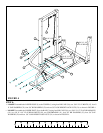
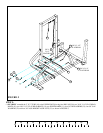
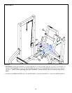
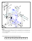
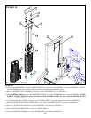
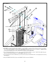
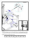
STEP 16:
FIGURE 16
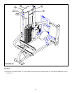
• Carefully route the CABLE around the pulley as shown. Make sure the CABLE is in the groove of the pulley.
3/8 X 1-3/4” 13
39
21
23
28
• SECURELY assemble the 4-1/2” PULLEY (39) to the vertical pulley bracket on the TOWER (1) using two RH CAPS (28), one
3/8 X 1-3/4” BOLTS (13), two 3/8” RH WASHERS (23), and one 3/8” LOW HEIGHT LOCK NUT (21).as shown in FIGURE
16.
• Carefully route the CABLE around the pulley as shown. Make sure the CABLE is in the groove of the pulley.
CABLE
1
5
3/8 X 1-3/4” 13
39
21
23
28
CABLE


