15
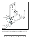
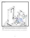
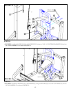
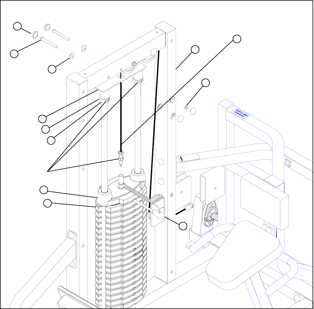
• Screw the threaded end of the CABLE half way into the end of the shaft on the HEAD PLATE (12) and tighten jam nut securely.
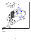
See FIGURE 13.
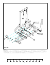
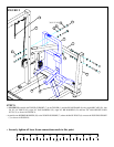
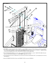
STEP 13:
FIGURE 13
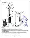
• Insert the WEIGHT STACK PIN (26) into the WEIGHT STACK as shown in FIGURE 13.
• SECURELY assemble the GUIDE ROD SUPPORT (4) to the TOWER (1) using four RH CAPS (28), two 3/8 X 2-1/2” BOLTS
(14), four 3/8” RH WASHERS (23) and two 3/8” LOW HEIGHT LOCK NUTS (21) as shown in FIGURE 13. (NOTE: Be sure
to route cable through the hole of the GUIDE ROD SUPPORT (8) before tightening.)
• Slide GUIDE ROD BUSHINGS (31) into the tubes on the GUIDE ROD SUPPORT (4), slide 1” SHAFT COLLARS (29) under-
neath the GUIDE ROD BUSHINGS (31) and SECURELY tighten the set screws.
TIGHTEN!
23
28
21
14 3/8 X 2-1/2”
4
31
29
1
26
36
12
1A


