12
0
1
2
345
6
1/2 1/2 1/2 1/2 1/2 1/2
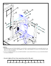
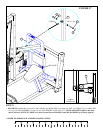
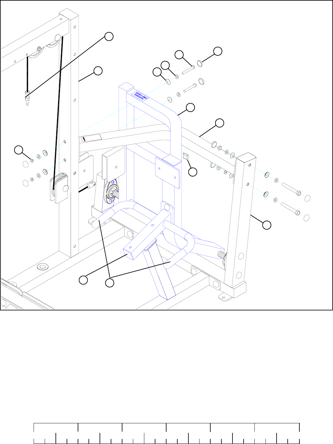
STEP 9:
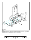
FIGURE 9
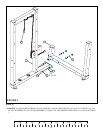
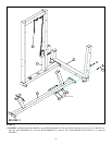
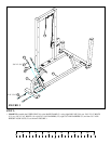
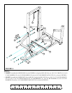
• SECURELY assemble the TOWER SUPPORT (7) to the TOWER (1) and the REAR FRAME (6) using eight RH CAPS (28), four
3/8 X 2-3/4” BOLTS (15), eight 3/8” SAE WASHERS (22), eight 3/8” RH WASHERS (23) and four 3/8” LOW HEIGHT LOCK
NUTS (21) as shown in FIGURE 9.
3/8 X 2-3/4” 15
23
22
6
1
21
30
7
5
28
• Assemble one RUBBER BUMPER (30) to the TOWER SUPPORT (7) where the BACK PIVOT (6) contacts the TOWER SUPPORT
(7) as shown in FIGURE 9..
• Securely tighten all loose frame connections made to this point.
1A
3B
3A


