


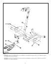
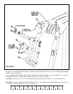
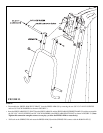

FIGURE 6
STEP 6:
9
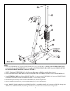
• SECURELY assemble the LEFT (D) and RIGHT (E) BOOM PLATES to the FRAME (A) using two 3/8 X 3-3/4” BOLTS (6) and
two 3/8” LOCK NUTS (19). See FIGURE 6.
• Slide up both SHAFT COLLARS (29) to top until fl ush with bottom of the guide rod bushings in both the LEFT (M) and RIGHT (N)
REAR UPRIGHTS and SECURELY TIGHTENas shown in FIGURE 6