3/8 X 1"
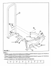
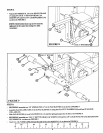
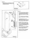
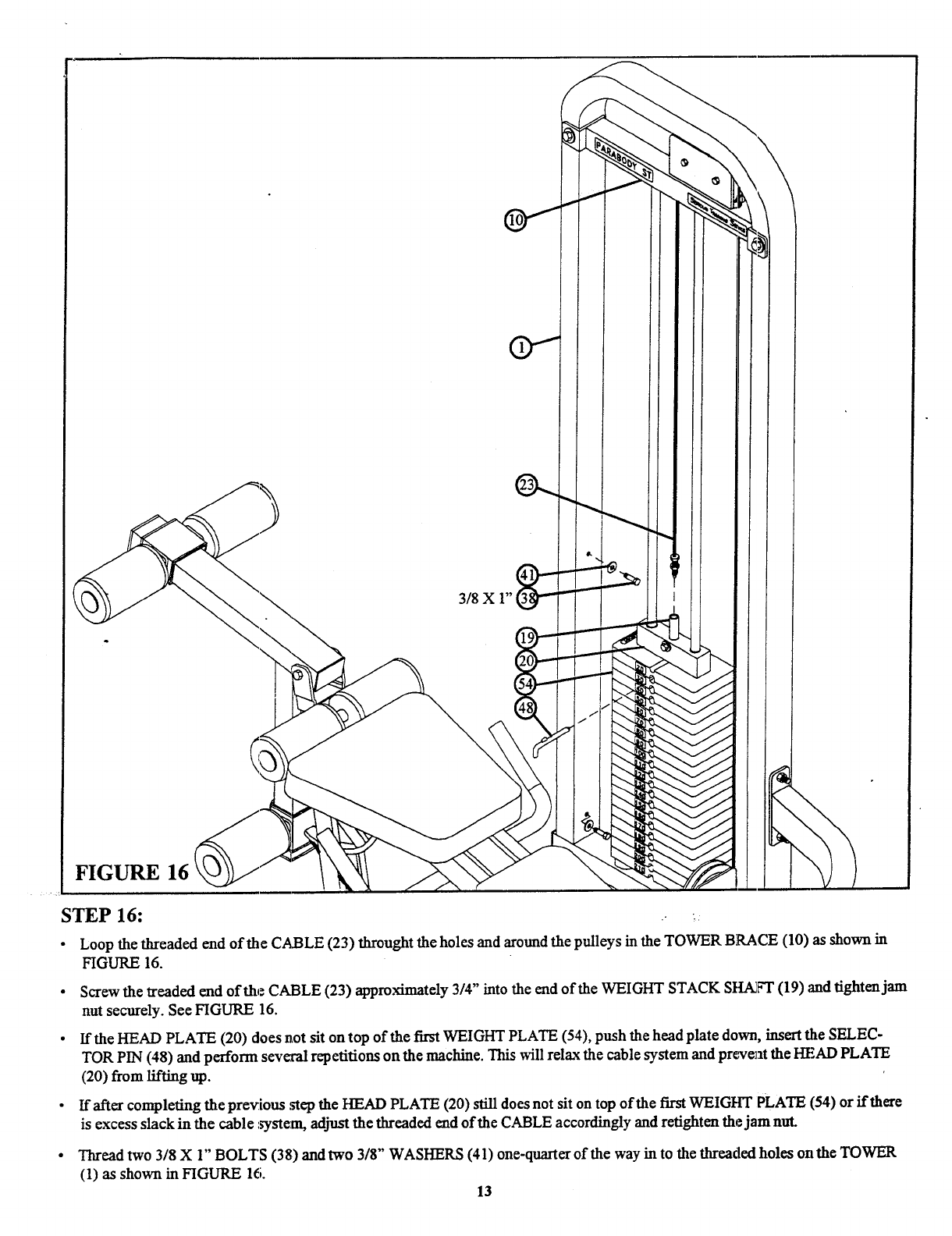
FIGURE 16
STEP 16:
.- ~.
¯
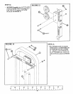
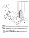
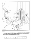
Loop the threaded end of the CABLE (23) throught the holes and around the pulleys in the TOWER BRACE (10) as shown
FIGURE 16.
¯
Screw the treaded end of the: CABLE (23) approximately 3/4" into the end of the WEIGHT STACK SHAdb’T (19) and tighten
nut securely. See FIGURE 16.
¯
If the HEAD PLATE (20) does not sit on top of the first WEIGHT PLATE (54), push the head plate down, insert the SELEC-
TOR PIN (48) and perform several repetitions on the machine. This will relax the cable system and preatent the HEAD PLATE
(20) from lifting up.
¯
If after completing the prex~ious .step the HEAD PLATE (20) still does not sit on top of the first WEIGHT PLATE (54) or if there
is excess slack in the cable :~ystem, adjust the threaded end of the CABLE accordingly and retighten the jam nut.
¯
Thread two 3/8 X 1" BOLTS (38) and two 3/8" WASHERS (41) one-quarter of the way in to the threaded holes on the TOWER
(1) as shown in FIGURE 16.
13


