


A S S E M B LY
I N S T R U C T I O N S
F R A M E A S S E M B L Y
Step 2c
FITNESS SYSTEMS
RR
O
H I
S
T
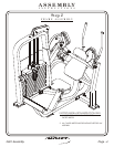
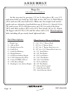
1 - Weight Cage
5 - Seat Frame Assembly
6 - Seat Support Mount
8 - Arm Support Assembly
9 - Range of Motion
10 - Cam Assembly Large
11 - Seat Adjuster
12 - Latch Assembly
13 - Aluminum Cap (Red Anodized)
Part Descriptions
D - 3/8”-16 x 1 1/4” Flat Head
CF - 3/8” x 2” Open Roll Pin
CG - Aluminum Cap
CJ - 1” OD Oilite Bushing
CK - Adjustment Spring
CL - 1/4” OD Pivot Shaft
CM - EZ-Glide Sleeve
CN - 1/2” Short Pull Pin
CP - Pull-Pin to Chain Link Connector
CQ - 2 x 4 End Cap
CR - 1/4” C-Clip
DR
R - Set Screw
CH - 1.00 Dia. 13.609 Shaft
- 3/8” Flat Head Cap (Red Anodized)
Hardware Descriptions
2601 Assembly
Page 11
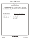
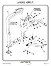
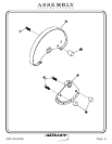
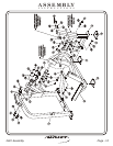
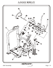
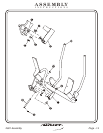
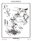
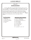
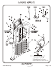
P Attach (10) to (CH), then slide (CH)
through (1) and attach to (9). Next, slide one side of (8) onto (CH), then
slide the other side of (8) through (6)
Hand tighten bolts only,
they will be tightened later.
ress two (CJ)’s into (8).
and secure. Attach (13) to (8) and
secure. Attach two (CM)’s to (5), and slide (11) into (5). Attach (12) to
(5). Secure (CN) to (8) and attach (CP) to (CN).