


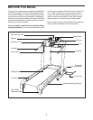
8
4.
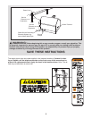
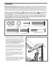
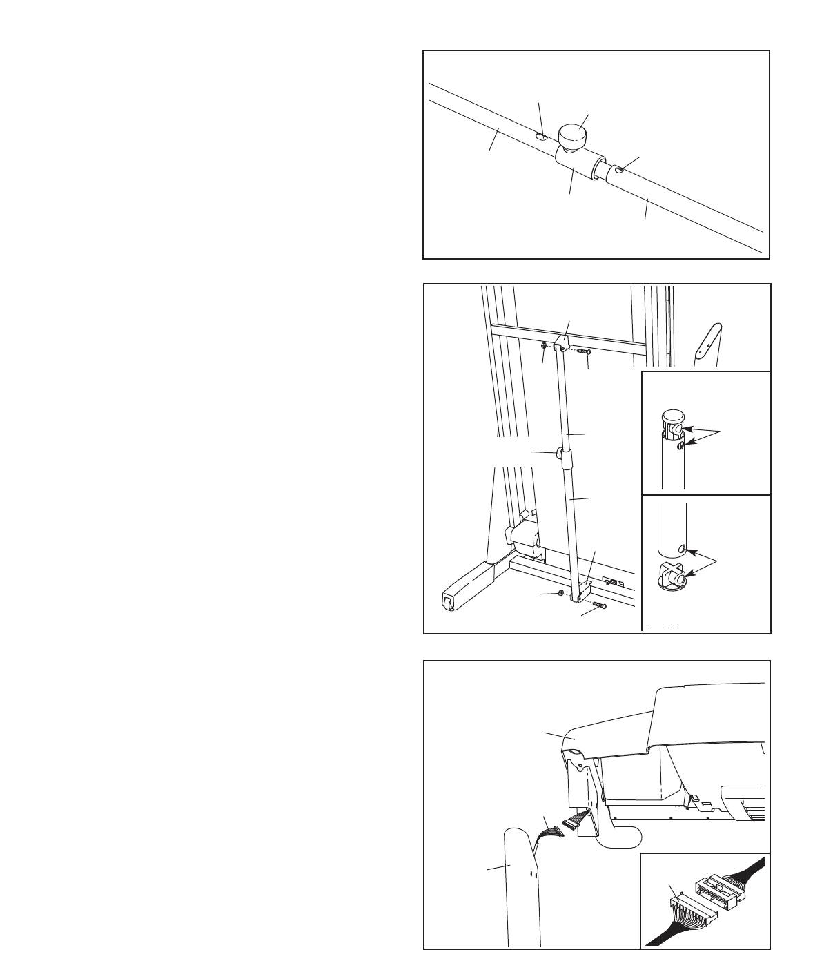
Remove the band securing the Upright Wire
Harness (73) to the right Upright (85). Have a
second person hold the console assembly near
the right Upright.
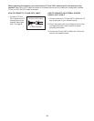
Connect the Upright Wire Harness (73) to the wire
harness extending from the console assembly.
See the inset drawing. The connectors
should slide together easily and snap into
place. If they do not, turn one connector and try
again. IF THE CONNECTORS ARE NOT CON
-
NECTED PROPERLY, THE CONSOLE MAY
BE DAMAGED WHEN THE POWER IS
TURNED ON. Then, insert the connectors into
the right Upright (85).
73
85
Console
Assembly
73
4
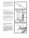
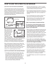
3. Remove the plastic ties from the ends of the
Latch Assembly (76).
Hold the Latch Assembly (76) with the large bar-
rel and the knob positioned as shown;
make
sure that all of the holes are aligned (see the
inset drawings). Next, attach the lower end of
the Latch Assembly to the bracket on the Upright
(85) with the Lower Latch Bolt (3) and a Nut (20).
Then, attach the upper end of the Latch
Assembly (76) to the bracket on the Frame (55)
with the Upper Latch Bolt (4) and a Nut (20).
Note: It may be necessary to move the Frame
back and forth to align the Latch Assembly with
the Bracket.
Lower the treadmill frame (see HOW TO LOWER
THE TREADMILL FOR USE on page 25).
76
20
20
Large
Barrel
85
3
55
3
4
Knob
Top
Bottom
Holes
Holes
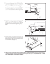
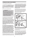
2. Identify the Latch Assembly (76). Make sure that
the sleeve has been slid over hole 1 and that the
k
nob is locked into hole 1. P
ull on the sleeve
to make sure it is locked into place.
Next, make sure that the knob (46) is locked into
hole 2. If it is not, pull out the tube until you see
hole 2 and then slide the tube back in until the
knob locks into hole 2.
2
Knob
Sleeve
Hole 1
Hole 2
Tube
76