


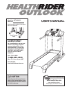

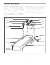
ASSEMBLY
A
ssembly requires two persons.
S
et the treadmill in a cleared area and remove all packing materials.
D
o not
dispose of the packing materials until assembly is completed. Note: The underside of the treadmill walking
belt is coated with high-performance lubricant. During shipping, a small amount may be transferred to the top of
the walking belt or the carton. This is a normal condition and does not affect treadmill performance. If there is lu-
bricant on top of the walking belt, simply wipe off the lubricant with a soft cloth and a mild, non-abrasive cleaner.
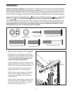
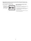
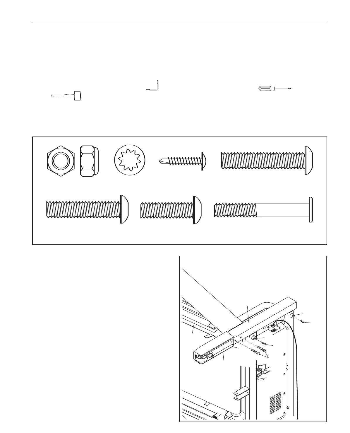
Assembly requires the included hex key and your own phillips screwdriver and rubber
mallet . For help identifying the assembly hardware, see the drawings below. The number in
parentheses below each drawing is the key number of the part, from the PART LIST near the end of this manual.
The number following the parentheses is the quantity needed for assembly.
Note: Some small parts may have
been preassembled. If a part is not in the parts bag, check to see if it has been preassembled. To avoid
damaging plastic parts, do not use power tools for assembly.
ew (123)–2
1/2” Silver Screw
(48)–1
3/4” Tek Screw (58)–4
3
S
pacer Screw (60)–2
1
1” Tek Screw (82)–4
3/8” Star
Washer (71)–4
5/16” Star
Washer (67)–4
2” Bolt (114)–4
2 1/4” Bolt (87)–4
Nut (20)–2
Extension Leg Bolt (87)–4
Console Bolt (72)–4
Upper Latch Shock Bolt (4)–1
Lower Latch Shock Bolt (3)–1
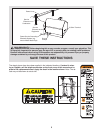
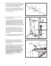
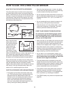
1. Make sure that the power cord is unplugged.
With the help of a second person, carefully tip
the treadmill onto its left side as shown. Partially
fold the Frame (55) so that the treadmill is more
stable. Do not fully fold the Frame until the
treadmill is completely assembled.
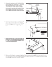
Insert an Extension Leg (97) into the base of the
Uprights (85) as shown. Tighten two Extension Leg
Bolts (87) into the bottom of the Extension Leg.
Attach two Base Pads (81) to the base of the
Uprights (85) with two 1” Tek Screws (82).
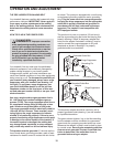
With the help of a second person, tip the tread-
mill over onto its right side. Attach the other
Extension Leg and Base Pads (not shown) as
described above.
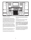
With the help of a second person, carefully raise
the treadmill so that all four Base Pads (81) are
on the floor and the Frame (55) is in a vertical
position (see the drawing in step 3).
97
85
55
81
1
7
81
82
82
87