


16
Figure 19
A
26
Faceplate
“Stems”
Figure 18
O
N
Rod Box
Brackets
Chest Bar
K
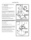
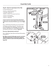
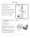
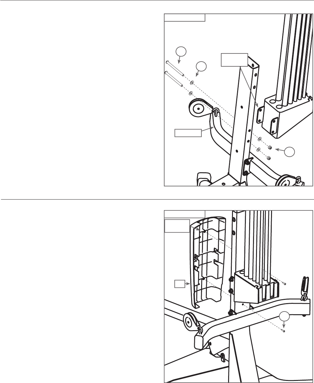
Step 18 - Attach the Rod Box Frame to the Lat Tower
Locate the following items:
• From Step 16 - Main Assembly
• From Step 17 - Rod Box/Frame Assembly
• Item #K - (2) 3/8" X 5" Button Head Screws
• Item #N - (4) 3/8" Washers
• Item #O - (2) 3/8" Nylock Nuts
Align the bolt holes on the Rod Box brackets with the bolt
holes on the Lat Tower above the Chest Bar , as shown in
Figure 18
.
Place (2) 3/8" Washers (Item #N) over the ends of
(2) 3/8" X 5" Button Head Screws (Item #K) - one washer per
screw. Insert the screws through the aligned holes. Place (1)
3/8" Washer and (1) 3/8" Nylock Nut (Item #O) over the end of
each screw and tighten.
Completely tighten hardware installed during Step 18.
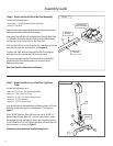
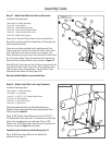
Step 19 - Attach the Faceplate to the Main
Assembly
Locate the following items:
• Item #26 - Faceplate
• From Step 18 - Main Assembly
• Item #A - (2) #10 Phillips Head Screws
Position the textured side of the Faceplate (Item #26) against
the Lower Lat Tower. Insert the plastic “stems” through the
corresponding holes on the Lower Lat Tower, as shown in Figure
19. You may need to push the Power Rods® out of the way to
insert the screws into the holes.
Attach the Faceplate to the Lower Lat Tower by threading (2)
#10 Phillips Head Screws (Item #A) into the “stems”.
Do not completely tighten hardware installed during Step 19 -
tighten screws approximately 1/2 of completion. Hardware will
be tightened during Step 20.
Assembly Guide