


Appendix A. Pinouts
A-2 TSU IQ+ User Manual 61200275L1-1
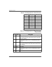
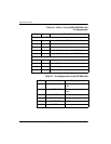
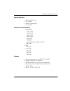
Table A-3. Pin Assignments for Control Connector
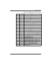
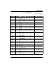
Table A-4. Pin Assignments for 10BaseT Connector
(Ethernet Card)
RJ Pin# Function Direction
1GND
2RTS I
3TD I
4DSR O
5RD O
6CTS* O
7DTR I
8DCD 0
* Used for hardware flow control.
Pin Name Description
1 TD+ The positive signal for the TD differential pair. This sig-
nal contains the serial output data stream transmitted
onto the network.
2 TD- The negative signal for the TD differential pair (pins 1
and 2).
3 RD+ The positive signal for the RD differential pair. This sig-
nal contains the serial input data stream received from
the network.
4, 5 N/A not used
6 RD- The negative signal for the RD differential pair (pins 3
and 6).
7, 8 N/A not used