7
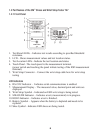
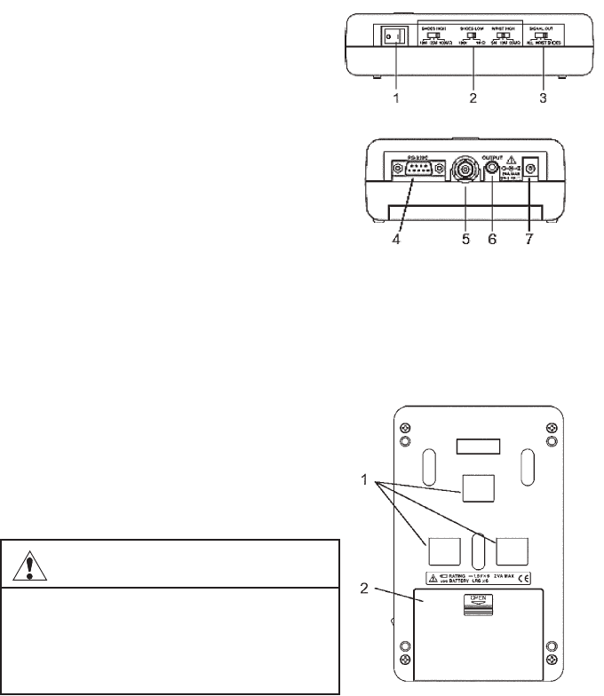
1.2.2 Side Panels
1.
Power Switch
–
Turns the 3M
™
Shoes and
Wrist Strap Tester 747 on and off.
2.
Threshold Resistance Selection Switches
– Select the threshold resistances for shoes
and wrist strap tests.
3.
Test Result Output Selection Switch –
Selects which test results are present at the
OUTPUT terminal.
4. RS-232C Connector
–
Connect to a PC serial
port using an RS-232C cable to transfer data.
5. ESD Shoe Testing
Cable Connector –
Connect to the supplied cable for shoe
testing. The other end of this cable connects
to the shoe testing plate.
6. Test Result OUPUT Jack
– Test results are available from this open-collector
output.
7. AC Adapter Input Jack – The supplied AC Adapter is connected here. Input
voltage is 9VDC, center positive.
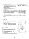
1.2.3 Back Side
1. Mounting Holes
–
These holes accommodate
the hooks on the supplied wall-mount board
for wall mounting.
2. Battery Cover
– To operate batteries, install
six “penlight” alkaline batteries under this
cover.
To reduce the risks associated with hazardous voltage,
which, if not avoided, may result in minor or moderate
injury and/or property damage:
• Not intended to be serviced by the user. No user
serviceable parts.
CAUTION


