


19
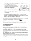
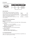
Pin Signal I/O Description
2 RxD IN Receiving Data
3
TxD OUT Sending Data
5 GND GND Signal Ground
Other pins are not used.
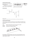
PC Connection
The RS-232C signal wires used are as follows (no other lines are used).
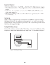
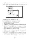
Cable Connections
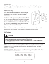
The 3M
™
Shoes and Wrist Strap Tester 747 connects
to the PC through a crossover cable. The transmit and
receive lines are crossed, and the ground lines connect
together. The other lines are ignored, but hardware flow
control must be disabled at the PC side.
Cable wiring at Shoes and Wrist Strap Tester 747 end:
cross-connected
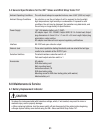
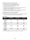
4.3 Card Reader Technical Specifications
Serial Interface Specification:
Bit Rate:
110, 300, 1200, 2400, 4800, 9600, 19200, 38400, 57600, 115200 (selectable)
Word Length:
Data Format – 4, 5, 6, 7, 8 (selectable)
Parity Bit – Even, Off, None, Mark, Space (selectable)
Stop Bit – 1, 1.5, 2 (selectable)
Handshaking (Flow Control):
None, Xon/Xoff, RTS/CTS, RTS/XonXoff (selectable)
Proximity Card Reader:
Message Indicator
Start of Text – Single ASCII Character
End of Text and CR – Single ASCII character
4.4 PC System Requirements
Check with 3M as PC System requirements and Software compatibility may
differ as new Operating Systems change.