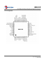
DM9161B
10/100 Mbps Fast Ethernet Physical Layer Single Chip Transceiver
Final 8
Version: DM9161B-12-DS-F01
January 31, 2008
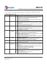
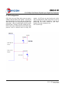
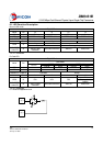
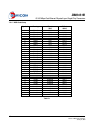
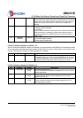
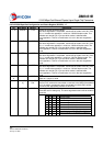
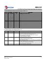
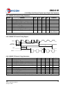
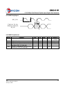
5.2 Media Interface, 4 pins
Pin No.
Pin Name
I/O
Description
3,4
RX+
RX-
I/O Differential Receive Pair
Differential data is received from the media
7,8 TX+
TX-
I/O Differential Transmit Pair
Differential data is transmitted to the media in TP mode
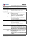
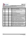
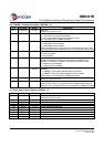
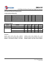
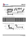
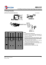
5.3 LED Interface, 3 pins
Pin No.
Pin Name
I/O
Description
11 LED0
/OP0
O,
LI
(U)
LED Driver output 0
OP0: (power up reset latch input)
This pin is used to control the forced or advertised operating mode of the
DM9161B according to the Table A. The value is latched into the
DM9161B registers at power-up/reset
This LED pin will “ON” for 500ms after reset de-assertion
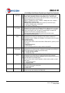
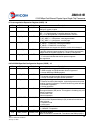
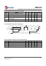
12 LED1
/OP1
O,
LI
(U)
LED Driver output 1
OP1: (power up reset latch input)
This pin is used to control the forced or advertised operating mode of the
DM9161B according to the Table A. The value is latched into the
DM9161B registers at power-up/reset
This LED pin will “ON” for 500ms after reset de-assertion
Note that, when this LED in “LED_mode=1” (see section 6.1)mode, it is
“ON” in 100Mbps mode even the DM9161B is not in link up state
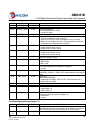
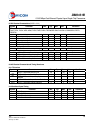
13 LED2
/OP2
O,
LI
(U)
LED Driver output 2
OP2: (power up reset latch input)
This pin is used to control the forced or advertised operating mode of the
DM9161B according to the Table A. The value is latched into the
DM9161B registers at power-up/reset
This LED pin will “ON” for 500ms after reset de-assertion
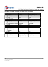
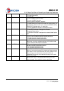
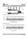
5.4 Mode, 3 pins
Pin No.
Pin Name
I/O
Description
10 PWRDWN I Power Down Control
Asserted high to force the DM9161B into power down mode. When in
power down mode, most of the DM9161B circuit block’s power is turned
off, only the MII management interface (MDC, MDIO) logic is available
(the PHY should respond to management transactions and should not
generate spurious signals on the MII)). To leave power down mode, the
DM9161B needs the hardware or software reset with the PWRDWN pin
low
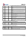
14 CABLESTS
/LINKSTS
O,
LI
(D)
Cable Status or Link Status
This pin is used to indicate the status of the cable connection when
power up reset latch low (Default)
0 = Without cable connection
1 = With cable connection
This pin is used to indicate the status of the Link connection when power
up reset latch high
0 = With link
1 = Without link