DM9161B
10/100 Mbps Fast Ethernet Physical Layer Single Chip Transceiver
Final 20
Version: DM9161B-12-DS-F01
January 31, 2008
Auto-Negotiation (continued)
Auto-negotiation also provides a parallel detection function for devices that do not support the Auto-negotiation
feature. During Parallel detection there is no exchange of configuration information, instead, the receive signal is
examined. If it is discovered that the signal matches a technology, supported by the receiving device, a connection
will be automatically established using that technology. This allows devices, which do not support Auto-negotiation
but support a common mode of operation, to establish a link.
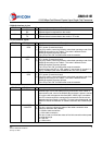
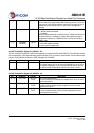
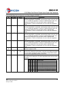
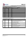
7.2.7 MII Serial Management
The MII serial management interface consists of a data interface, basic register set, and a serial management
interface to the register set. Through this interface it is possible to control and configure multiple PHY devices, get
status and error information, and determine the type and capabilities of the attached PHY device(s).
The DM9161B management functions correspond to MII specification for IEEE 802.3u-1995 (Clause 22) for
registers 0 through 6 with vendor-specific registers 16, 17, 18, 21, 22, 23 and 24.
In read/write operation, the management data frame is 64-bits long and starts with 32 contiguous logic one bits
(preamble) synchronization clock cycles on MDC. The Start of Frame Delimiter (SFD) is indicated by a <01>
pattern followed by the operation code (OP) :< 10> indicates Read operation and <01> indicates Write operation.
For read operation, a 2-bit turnaround (TA) filing between Register Address field and Data field is provided for
MDIO to avoid contention. Following the turnaround time, 16-bit data is read from or written onto management
registers.
7.2.8 Serial Management Interface
The serial control interface uses a simple two-wired serial interface to obtain and control the status of the physical
layer through the MII interface. The serial control interface consists of MDC (Management Data Clock), and MDI/O
(Management Data Input/Output) signals.
The MDIO pin is bi-directional and may be shared by up to 32 devices.
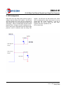
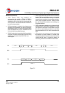
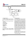
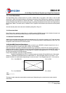
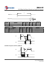
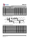
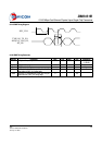
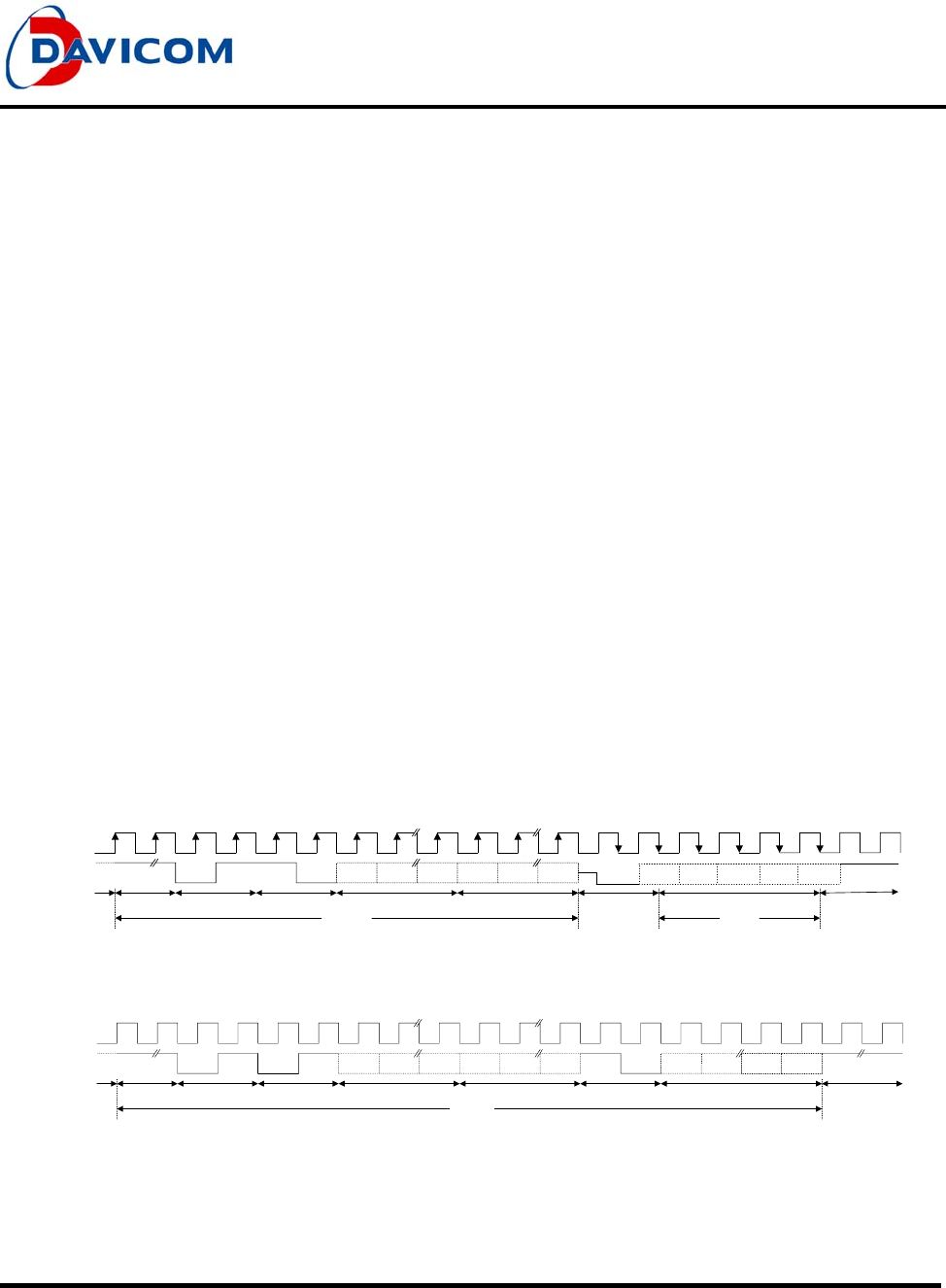
7.2.9 Management Interface - Read Frame Structure
32 "1"s
0 1 1 0 A4 A3 A0 R4 R3 R0
Z
0
Idle Preamble SFD Op Code PHY Address Register Address Turn Around Data Idle
Read
Write
MDC
MDIO Read
D15 D14 D1 D0
//
//
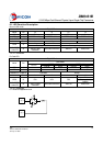
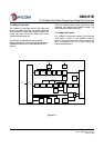
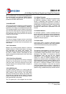
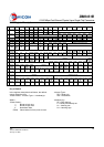
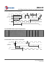
7.2.10 Management Interface - Write Frame Structure
32 "1"s 0 1 10 A4 A3 A0 R4 R3 R0 1 0 D15 D14 D1 D0
Idle Preamble SFD Op Code PHY Address Register Address Turn Around Data Idle
Write
MDC
MDIO Write
Figure 7-5