Attaching the computer wire
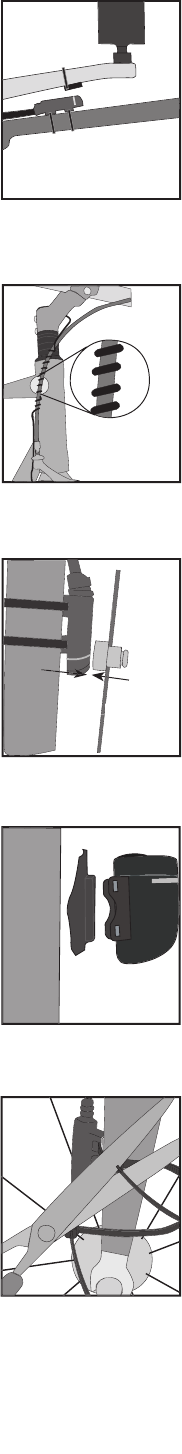
The computer wire is usually longer than needed. Extra wire length can be
diverted by wrapping it around the brake housing prior to routing it down the fork
blade or down tube (Figure 9).
Make sure the computer wire is not pulled tight when the handlebar is turned all
Wireless computers do not have wires. For wireless computers, see
To attach the computer wire
1. Determine the length of wire to divert by holding the sensor at its desired
2. Wrap the wire around the front brake cable, diverting the determined amount.
3. Continue routing the wire, either by wrapping around the fork or frame tube, or
attach the wire to the fork or frame tube with electrical tape.
4. As needed, solidify the wire attachment with either nylon ties or electrical tape.
These instructions are written for the front wheel, but apply equally to installing
the magnet and cadence sensor which go on the left crank and the frame’s
1. Align the sensor with the magnet.
The magnet must pass across the line on the sensor (Figure 10).
2. Orient the sensor so that the clearance between the sensor and the magnet is
The sensor can be rotated around the fork blade or crank about 45 degrees.
If needed, the sensor and magnet can be moved up or down the fork and wheel to change the
3. For the wireless sensor, install the rubber “foot” in the sensor (Figure 11).
4. Attach the sensor with nylon ties, but do not fully tighten.
5. With the computer in the computer base, check the alignment of the sensor and
magnet by spinning the wheel and noting if the computer is displaying speed.
If the computer shows current speed, the sensor is reading the magnet. If the computer is not
displaying current speed, realign the sensor and magnet until current speed is displayed.
6. Tighten the nylon ties and trim the excess length (Figure 12).
sor, foot, and fork blade


