


2
INSTALLATION
Tools needed:
• Electrical tape
• Slot-type screwdriver
• Phillips-type screwdriver
• Scissors
This section explains the steps to install your computer onto your bicycle:
• Placing the computer on the handlebar
• Placing the magnet and sensor(s) on the bike
Placing the computer on the handlebar
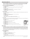
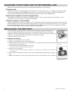
The Trek Incite computer can be mounted on the handlebar or on the stem (Figure
3).
To install the computer on the handlebar
1. Determine your bicycle’s handlebar diameter: 22.2mm, 25.4/26.0mm, or 31.8mm.
2. Select the corresponding bar clamp
For a 22.2mm bar, use the rubber shim (provided) inside the smaller clamp.
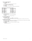
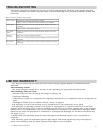
3. Insert the handlebar clamp into the back of the computer base (Figure 4) and
slide it towards the front of the base.
4. Insert the rubber friction pad into the computer base, aligned across the
computer base.
5. With the wire pointing toward the front of the bike, wrap the bar clamp around
the handlebar.
6. Insert the screw through the washer and into the computer base.
7. Tighten the screw until the computer base cannot rotate on the handlebar.
8. Slide the computer into the computer base until the front of the computer and
computer base line up.
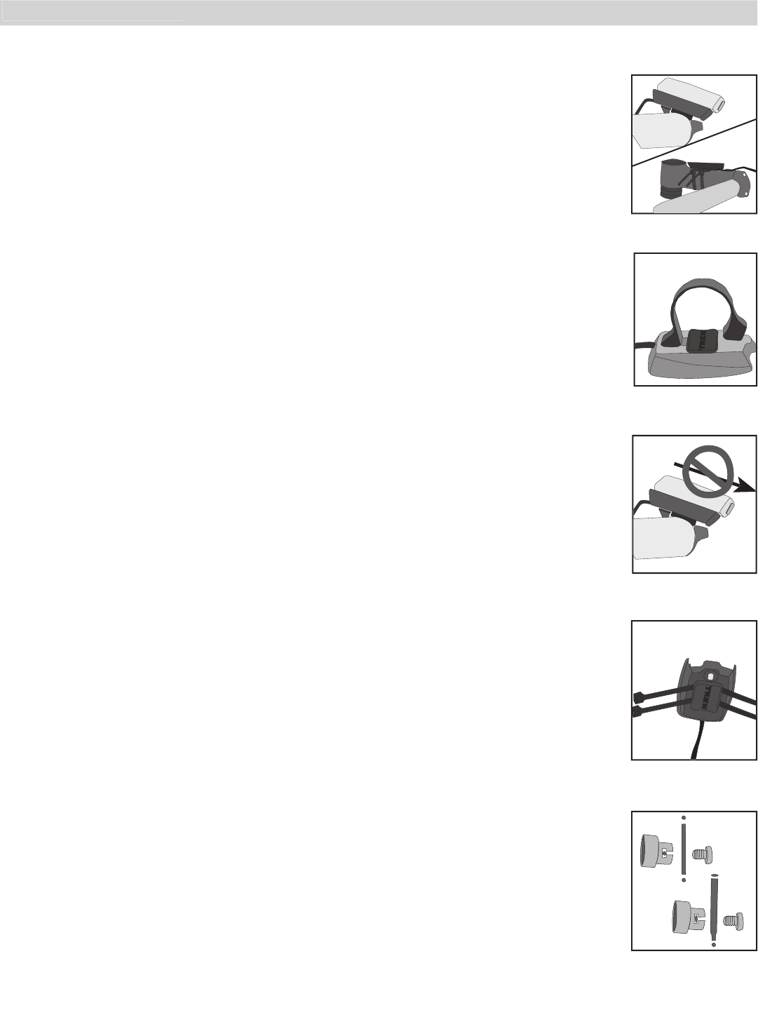
9. Check that the computer base cannot be rotated around the handlebar, and that
the computer cannot slide backwards on the computer base (Figure 5).
To install the computer on the stem
1. Insert the rubber friction pad into the computer base, aligned along the
computer base.
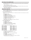
2. Insert two nylon ties through the computer base (Figure 6).
3. Place the base on the stem and tighten the nylon tie.
4. Slide the computer into the computer base until the front of the computer and
computer base line up.
5. Check that the computer base cannot be rotated around the stem and the
computer cannot slide backwards on the computer base.
6. Tighten the nylon ties and trim the excess length.
Placing the magnet and sensor(s) on the bike
The wheel magnet must be aligned so that it passes across the sensor. As the
magnet passes the sensor, it must be no further from the sensor than 1 to 3mm (1/
32 to 1/8 inch).
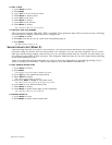
The wheel magnet has a ‘T’ shaped slot with two configurations: round spokes and
flat or bladed spokes (Figure 7).
Computers with the cadence function have two sensors. The shorter computer
wire is for the cadence sensor which mounts near the crankset. The sensor must be
aligned so that the magnet passes within 1-3mm of the sensor, and in line with
the small line on the sensor (Figure 8).
To install the magnet
1. Remove the screw from the magnet.
2. Slide the slot in the back of the magnet over the spoke.
For a flat or bladed spoke, start the spoke near the end where the spoke is round, and align the
top of the ʻTʼ with the spoke as you slide the magnet up the blade.
3. Thread the screw into the magnet until it is snug against the spoke.
Installation
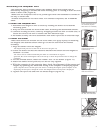
Figure 6- Nylon tie
threaded through com-
puter base
Figure 7- Magnet placed
on round and oval
spokes
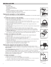
Figure 3- Computer on
handlebar and stem
Figure 4- Clamp and
friction pad in computer
base
Figure 5- Make sure the
computer cannot be
bounced off.