


ABS-PRC001-EN34
Job Site
Connections
Steam Supply and
Condensate Piping
Steam Supply
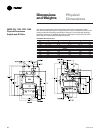
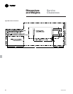
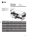
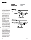
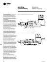
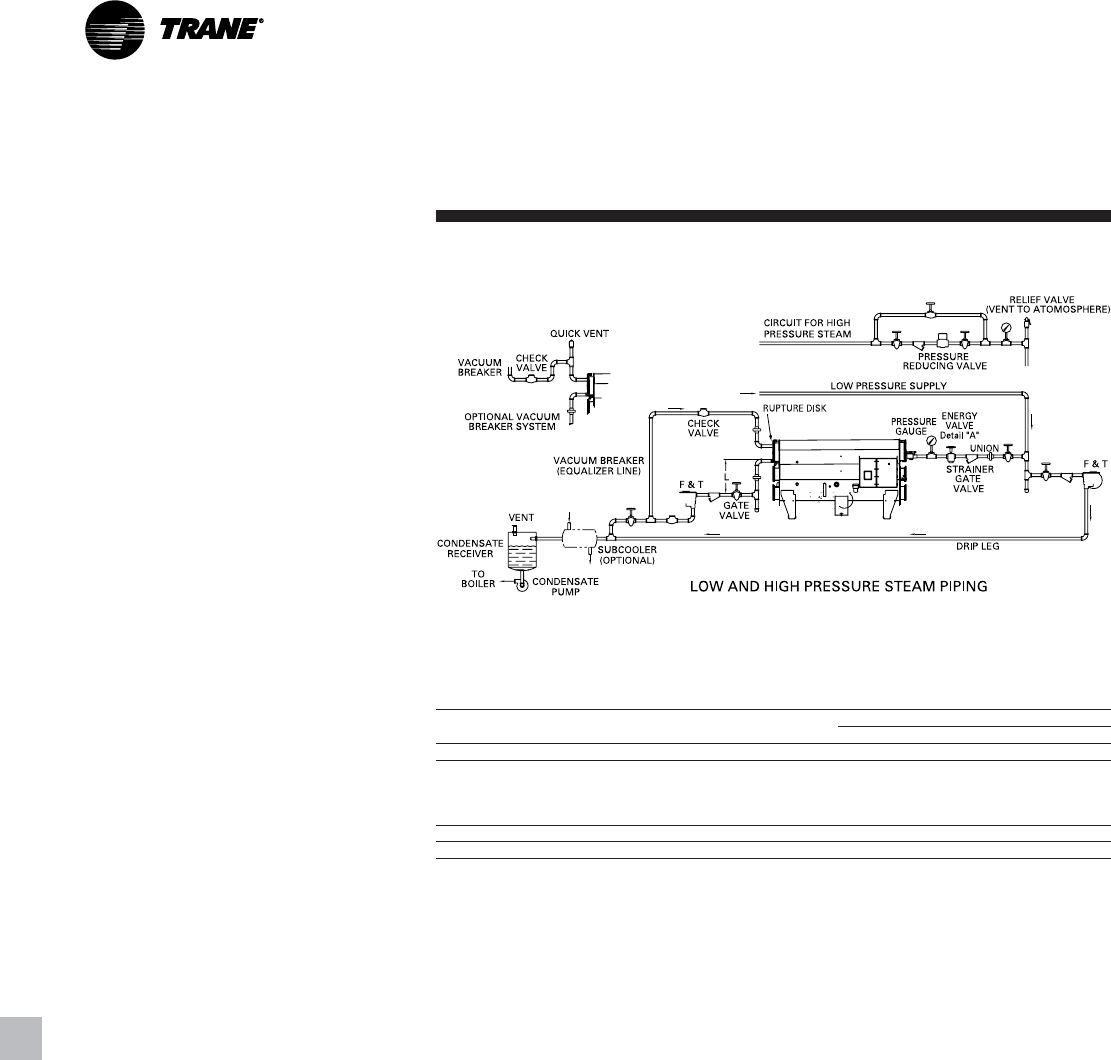
Figure JC-1 illustrates a typical steam-
supply piping illustration that includes
the appropriate hardware.
The steam supply piping should be
designed in accordance with good
design practice, providing strainers,
unions and gate valves for ease of
operation and maintenance. A properly
sized steam-modulating valve, based on
design flow and pressure drop
requirements, is provided by The Trane
Company.
A hand valve in the steam supply piping
is recommended when the machine will
be out of operation for an extended
period. The modulating steam valve
may experience a small amount of
leakage during shutdown. This leakage
may result in heating of the equipment
room unless the machine is properly
isolated with a hand valve.
In all applications, it is recommended
that the steam supply pressure to the
control valve inlet not exceed design to
ensure that the valve closes properly. If
steam supply pressures exceed design, a
pressure reducing station should be
used to control the steam pressure to the
valve.
The unit control has adjustable features
that minimize steam draw on start-up.
The adjustable steam-control feature
allows the user to adapt the machine to
the available steam source capability.
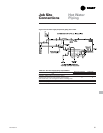
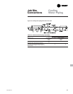
Table JC-1. Steam supply and condensate return piping responsibilities
Material Provided By Installed By
Item Trane Other Trane Other
Energy Valve X X
T-Type Strainer, Flanged connections, gate valve, drip leg
w/dirt pocket, float and thermostatic trap, pressure gauge vent X X
and valve, pressure reducing valve, pressure gauge, relief valve
check valve, connecting piping.
Rupture Disk Assembly X X
Rupture Disk Piping X X
Figure JC-1. Typical steam supply piping