


ASSEMBLY INSTRUCTIONS
8
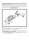
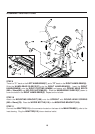
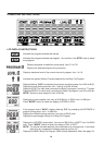
STEP 5
Connect the LOWER CONNECTION WIRE(30) to UPPER CONNECTION WIRE(31). Insert the
UPRIGHT(4) into the MAIN FRAME(1) and secure with SOCKET HEAD BOLTS(M8 x 25mm)(70),
SOCKET HEAD BOLTS(M8 x 50mm)(71), and LOCK WASHERS(M8)(88).
The opening in the channel on the UPRIGHT(4) must be facing toward the back as shown.
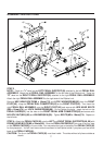
If necessary, loosen the mounting
SCREWS(M4 x 20mm)(76) for the LEFT and RIGHT
UPRIGHT COVERS(13, 14) to provide additional space for the UPRIGHT(4). Re-tighten these
screws after the
UPRIGHT(4) is assembled.
NOTE:
HINT:
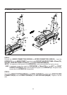
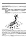
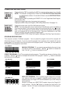
STEP 6
Connect the RIGHT PIVOTING ARM(94) to the PEDAL SLIDER(51) by attaching the RIGHT SLIDER
CONNECTOR(92) onto the PEDAL SLIDER(51) with NYLOCK NUTS(M8)(85). Repeat on the left
side.