ASSEMBLY INSTRUCTIONS
11
STEP 9
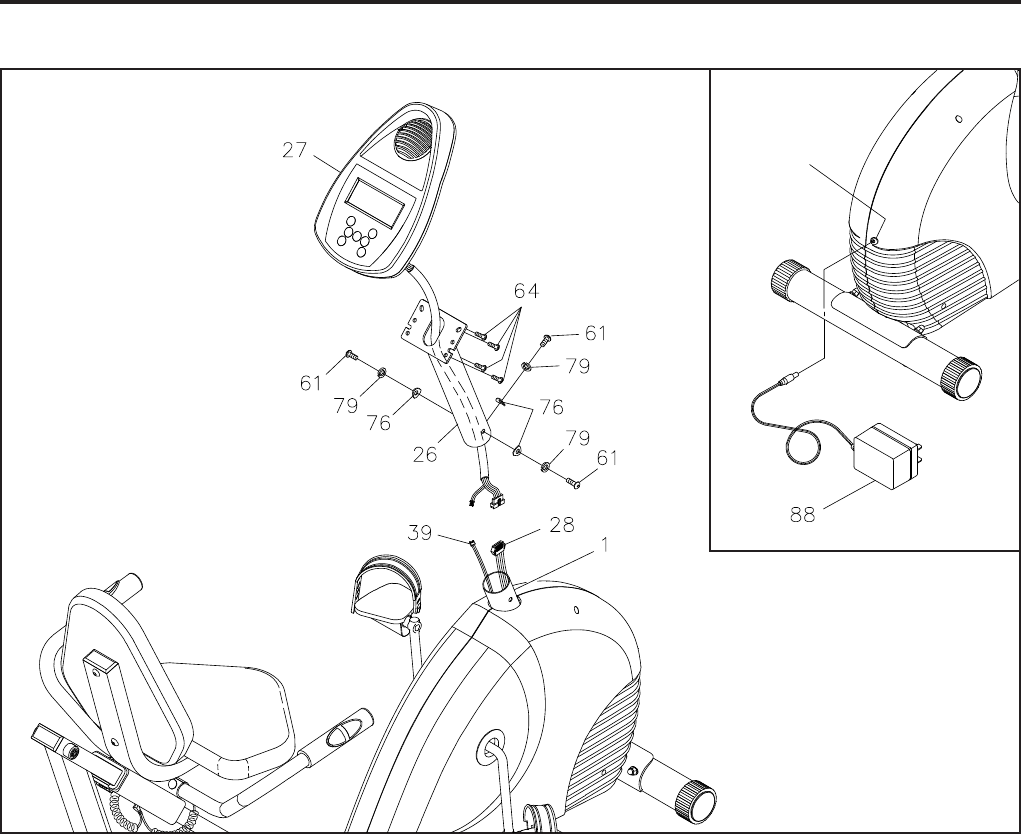
Run the EXTENSION WIRE on the COMPUTER(27) through the COMPUTER POST(26). Attach the
COMPUTER(27) to the COMPUTER POST(26) with ROUND HEAD SCREWS(M5x0.8x12mm)(64).
STEP 10
Plug the MOTOR CONTROL WIRE(28) and PULSE PLUG WIRE(39) to the EXTENSION WIRE on the
COMPUTER(27). Insert the COMPUTER POST(26) onto the FRONT FRAME(1) and secure with ROUND
HEAD BOLTS(M6x1x15mm)(61), LOCK WASHERS(M6)(79), and ARC WASHERS(M6)(76).
NOTE: Be careful not to damage the wires when attaching the COMPUTER(27).
STEP 11
Refer to the inset drawing. Plug the ADAPTER(88) into the SOCKET of the POWER WIRE(86) located on
the front of the bike. Plug the ADAPTER(88) into an electrical outlet.
Socket of
Power
Wire(86)


