


8
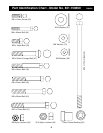
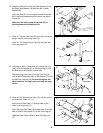
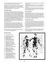
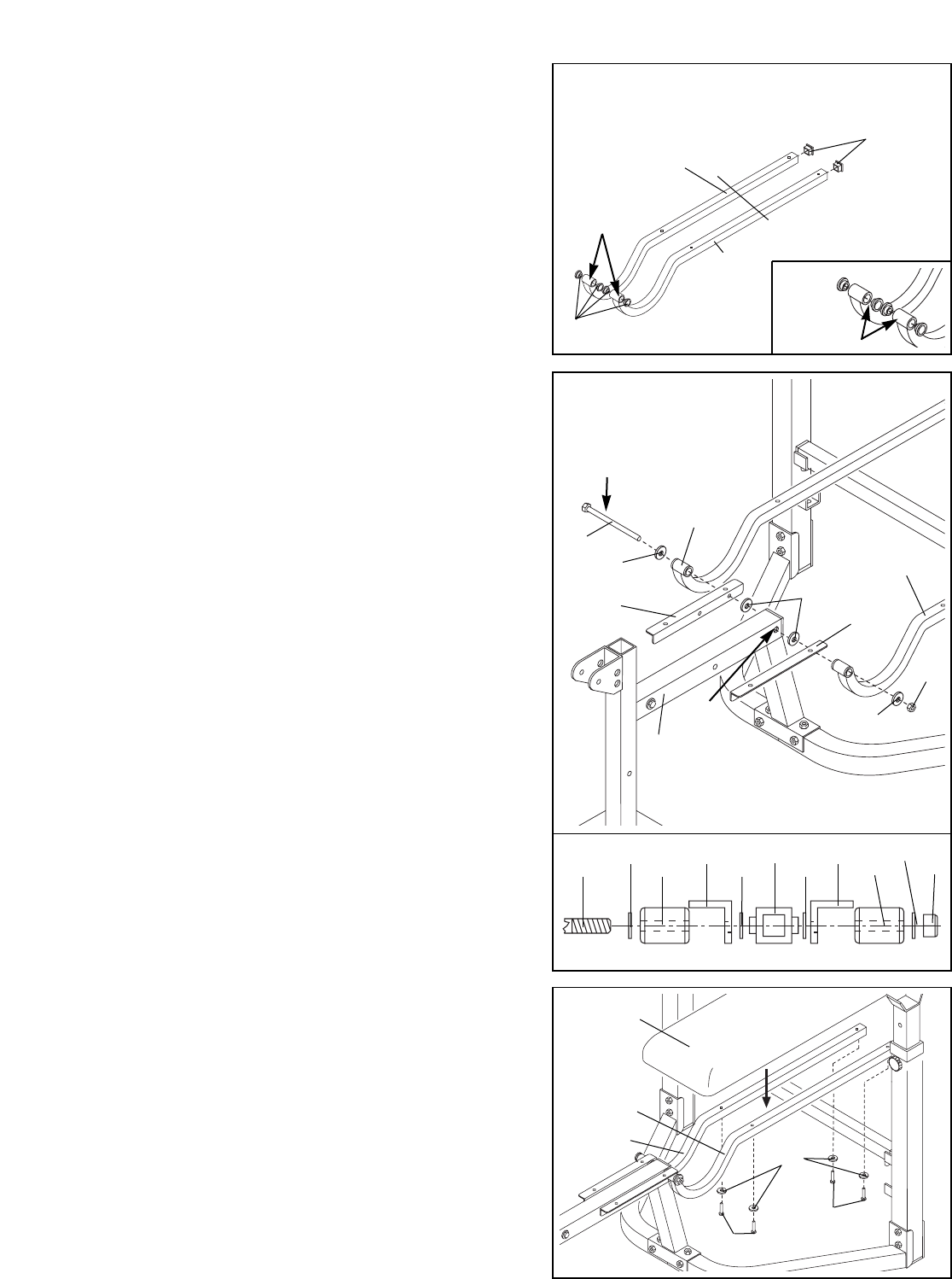
7. Insert a 1” Square Inner Cap (32) into the open end
of each Backrest Tube (13, 14).
Insert a 10mm Plastic Bushing (35) into each end of
the welded tubes on the Backrest Tubes (13, 14) as
shown in the inset drawing.
Identify the Left (13) and Right (14) Backrest Tube.
The welded tube on the front end extends on one
side. This protrusion must be pointed towards the
center of the bench as shown in the inset draw-
ing.
7
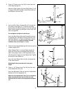
8. Refer to the inset drawing for this step.
Lubricate an M10 x 175mm Bolt (43) and slide an
M10 Washer (37) onto it. Push the Bolt through the
welded tube on the Left Backrest Tube (13).
Insert the Bolt through the indicated hole in the Left
Seat Bracket (1). Make sure you have identified the
Left Seat Bracket and that it is oriented as shown
in the drawing.
Slide a Plastic Spacer (20) onto the M10 x 175mm
Bolt (43). Push the Bolt through the holes (D) in the
Bench Frame. Slide another Plastic Spacer (20) onto
the Bolt.
Insert the M10 x 175mm Bolt (43) through the indicat-
ed hole in the Right Seat Bracket (19). Make sure
you have identified the Right Seat Bracket and
that it is oriented as shown in the drawing.
Push the M10 x 175mm Bolt (43) through the welded
tube on the Right Backrest Tube (14). Secure it with
an M10 Washer (37) and an M10 Nylon Locknut (49).
Do not overtighten the Nylon Locknut. You must
be able to freely pivot the Backrest Tubes (13, 14)
and Seat Brackets (1, 19).
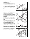
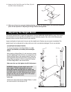
9. Attach the Backrest (23) to the Left Backrest Tube
(13) and the Right Backrest Tube (14) with four M6 x
40mm Bolts (44) and four M6 Washers (36).
8
9
13
14
32
43
13
5
37
Lubricate
37
D
49
14
44
44
23
36
13
14
20
1
19
35
43
37
13
1
20
5
20
19
14
37
49
Protrusion
Welded
Tubes
23