


7
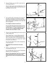
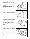
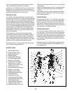
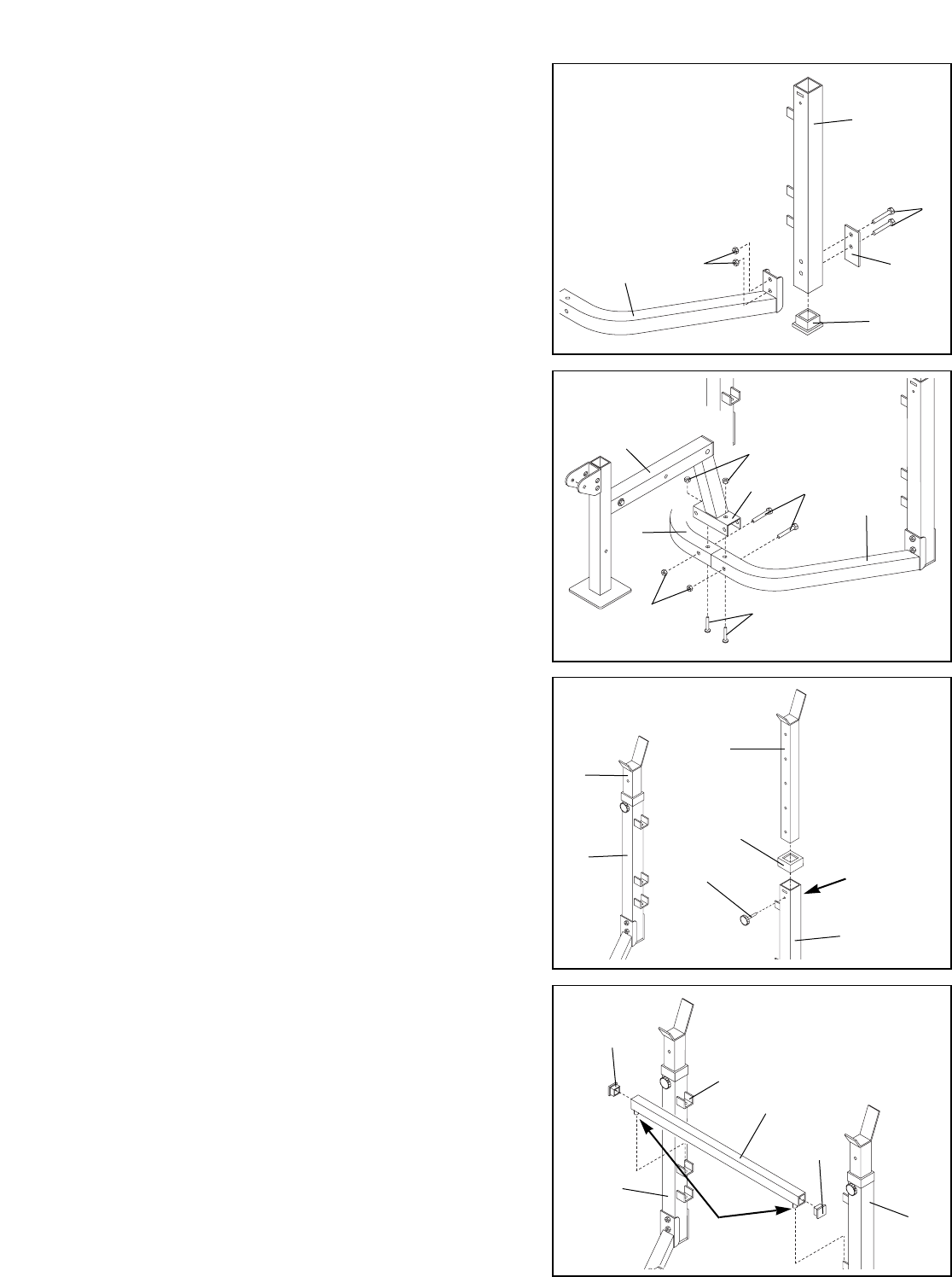
3. Press a 2” Square Inner Cap (29) into the lower end
of the Right Upright (9).
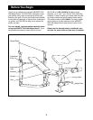
Attach the Right Upright (9) to the Right Base (7) with
a Support Plate (28), two M8 x 65mm Bolts (42) and
two M8 Nylon Locknuts (40).
4. Insert an M8 x 55mm Carriage Bolt (47) through the
front hole in each Base (6, 7). Slide the mounting
bracket (B) on the Bench Frame (5) onto the Carriage
Bolts. Partially tighten an M8 Nylon Locknut (40) onto
each Carriage Bolt.
Do not tighten the Nylon Locknuts yet.
Insert two M8 x 60mm Bolts (48) through the mount-
ing bracket (B) on the Bench Frame (5) and the Left
and Right Base (6, 7). Tighten an M8 Nylon Locknut
(40) onto each Bolt. Tighten the Bolts (39) and
Locknuts (40) used in steps 1–4 now.
4
42
40
7
29
28
9
40
48
5
47
40
7
6
B
3
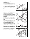
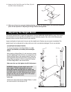
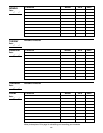
5. Press an Outer Upright Bushing (46) onto the top end
of each Upright (8, 9).
Slide a Weight Rest (11) into the Right Upright (9).
Align one of the holes in the Weight Rest with the
hole in the Upright. Insert an M10 Adjustment Knob
(25) through the Upright and the Weight Rest. Tighten
the Knob into the welded nut.
Insert the other Weight Rest into the Left Upright (8)
in the same manner.
Both Weight Rests must be set at the same
height.
5
Welded Nut
46
25
8
11
11
9
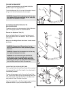
6. Press a 1 1/4” Square Inner Cap (34) into each end
of the Adjustment Tube (12).
Insert the Adjustment Tube into one set of adjustment
brackets (C) on the Uprights (8, 9).
Make sure the Adjustment Tube (12) is oriented as
shown and that the pins on the Tube are fully
inserted into the slots in the adjustment brackets
(C).
6
8
C
34
34
9
12
Pin