


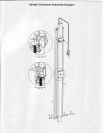
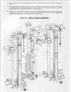
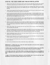
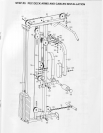
STEP # 1: MAIN FRAME ASSEMBLY
1. Place the two
Base Rails
(1
& 2) opposite each other
in the center of the assembly area as shown
in the
lllustration. Place the Lower Cross Brace
(3)
between the two
Base Rails
(1
&
2) so
that
the side
pre-drilled
holes
of the
Base Rails
(1
& 2) align with the end
holes of the Lower Cross Brace
(3).
2. Carefully
thread the Cross
Brace Wire Harness
(8)
through
the
corresponding
side
pre-drilled
holes of the Base
Rails
(1
& 2) then
pull
the
Wire Harness
(8)
out
of the top holes of the Base
Rails
(1
& 2).
3. Attach the
two Base Rails
(1
&
2)
to the
Lower Cross Brace
(3)
using two Cross
Brace Backing Plates
(13),
four
bolts
(22),
eight
washers
('18)
and four nuts
(20)
as shown.
HAND TIGHTEN the bolts at this time.
4. Attach the
Right Upright Guidepost
Assembly
(7,
10, 23\ to the Right Base
Rail
(2)
using two Upright Support
Plates
(6),
four bolts
(22),
eight
washers
(18)
and four
nuts
(20)
as shown.
HAND TIGHTEN
the bolts at this time.
5. Attach the
Left Upright Guidepost Assembly
(9,
12, 23) to the Left Base Rail
(1)
using
two
Upright
Suppurt Plates
(6),
four
bolts
(22),
eight washers
(18)
and
four nuts
(20)
as shown. HAND TIGHTEN the bolts
at this time.
6. Slide the
VKR Sliding Adjuster
('111)
up onto
the left one of Rear Uprights
(4)
as shown. Pull the handle
on the
screw down
pull pin
(68)
previously
installed. This will allow the
VKR
Sliding Adjuster
(11'l)
to slide
up.
Release
the
pin
to
lock
in
place
and secure
by turning knob clockwise.
7. Attach the VKR Frame
(59)
to the
VKR Sliding Adjuster
(111)
using
two
bolts
(110)
four washers (18)
and
two
nuts
(20)
as shown.
Tighten the bolts securely.
8. Attach the left Rear Upright
(4)
to the Lower Cross
Brace
(3)
and lhe Cross
Brace Backlng Plate (13)
attached on
the Left Base Rail
(1)
using two bolts
(22),
four washers
(18)
and two nuts
(20)
as shown.
HAND
TIGHTEN
the
bolts at this time.
9. Slide the Chin-up Bar Sliding Adjuster
(1
12) up onto the right one
of
Rear Uprights
(4)
as shown Pull the handle
on the screw
down
pull pin
(68)
previously
installed.
This will allow the Chin-up Baf S
id ng Adtuster (1
'12)
to slide
up. Release the
pin
to lock in
place
and secure by turning
knob
clockwise.
10. Attach the Chin-up Bar(61) tothe Chin-up BarSliding Adjuster
(1
1 2) using two bolts
(
1 1
0)
fourwashers
('18)
and
two nuts
(20)
as shown.
Tighten
the bolts securely.
1 1 . Attach the right Rear Upright
(4)
to the Lower Cross Brace
(3)
and the Cross Brace Backrng Plate
(13)
attached
on the Right Base Rail
(2)
using two bolts
(22),
four washers
(18)
and two
nuts
(20)
as sholvn
HAND TIcHTEN
the bolts at this time.
12. Plug
together
both of
the
Cross Rail Wire Harness
(8)
to
lower
ends of the Spiral Signal Cables
(46)
located
just
under the
perforated
Slider Shields on back of the Screen
Panels
(23).
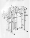
'13.
Attach one Pulley
Support
Frame
(17)
to the
Left
Upright
Guide Post
(12)
using two bolts
(22).
four
washers
(18)
and two
nuts
(20).
HAND TIGHTEN
the bolts at this time.
'14.
Carefully thread the Left Weight Bar Knuckle
(44)
up through
the
rectangular
cutout in the Pulley
Support Frame
(17).
Carefully flex the Left Weight Bar Cables
(24)
so that the cables
are between the iwo
puliey
support
plates
and insert into the
grooves
of each
corresponding
pulleys.
Be sure
that the cables are straight and
uncrossed
and
pulleys
move smoothly.
15. Attach
the
two small
plastic pipes
(15)
to the
Pulley
Support
Frame (17)
using
two bolts
(34).
four
washers
(38)
and two nuts
(35)
as shown. Tighten
the bolts
securely.
16.
Repeat steps 11-13 on the right side of
the
PROSPOTlirrressrM P-500.
'17.
Attach
the two Rear Uprights
(4)
and the Top Beam
(60)
to the two Pulley
Support Frames
(17)
using four
bolts
(28),
eight washers
(18)
and four nuts
(20)
as shown. HAND
TIGHTEN
the bolts
at
this
time.
18. Attach
the
Pec Deck
Support Post
(16)
and the Electronic Box Locating
Plate
(5)
to the Lower
Cross Brace
(3)
using
two
bolts
(22),
four washers
(18)
and two nuts
(20)
as shown.
HAND TIGHTEN the bolts
at this time.
19. Attach the Pec Deck
Support Post
(16)
to the Top Beam
(60)
using
a bolt
(51),
two washers
(18)
and
a
nut
(20)
as shown. HAND TIGHTEN
the bolts at this time.
20. Tighten
all bolts and nuts used for
assembly
in
previous
steps.
21.
Insert both of the
Guide
Rods
(77)
into each of the Guide Rod Cups
(74)
located
on the lower end
of the
Pec
Deck Support Post
(16).
Slide the Weight Stacks
(67)
onto
the
Guide Rods
(77)
and
carefully
slide
them to the
bottom. Slide the Weight Top
Plate Assembly
(63,
70) onto the Guide Rods
(77)
and
guide
them down
so that
they rest on top of the Weight
Stacks
(67).
Insert two Allen bolts
(71)
into
the threaded holes in the Guide Rod
Cup Pockets of the Pec Deck
Support Post
(16).
Tighten securely.