


-- 6 --
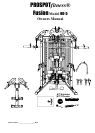
Instructions for Assembly of the ProSpotfitness® HG-5 (Con’t.)
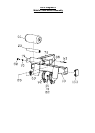
Step #4 WEIGHT BAR ASSEMBLY
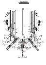
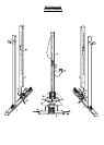
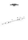
1. Now its time to install Sensor Weight Bar (34). Reference Diagram 11. Using a 5mm allen wrench remove
the M8*40 Screw (121) Head Screw &
End Cap (45) off each end. Now using a 4mm allen wrench, remove
the Spacer Collar (48) from each end of Sensor Weight Bar. Next remove the Rotating Loop (113) with the
steel spacer bushings. Set these parts aside for the moment.
2. This may take two people to perform this next task. Place Sensor Weight Bar in front of unit. Grab and touch
both at the same time the metal plate on the Weight Bar Cable Knuckles (128 & 129) that are on the front of
the unit. This will trigger the sensor to release the Cables to allow down ward movement. Pull down to waist
level and hold these at this position. Make sure Cables are not twisted and the metal face of Cable Knuckle
is facing inward. If you let go the Cables, they will retract back into unit. Now have your assistant slide end of
the (34) Sensor Weight Bar thru holes in knuckles on each side. Note: There is a key slot cut out in Cable
Knuckle for a metal pin on Sensor Weight Bar to slide thru. You can now let go of Sensor weight Bar. It will
not move unless Sensor is triggered.
3. Now reinstall Rotating Loop (113) with the steel spacer bushings. (The same way they came off.) Next install
the Spacer Collar (48) so that it is against the Rotating Loop (113) bushing and tighten with 4mm Allen
wrench. Now install the Olympic adapters (35), End Caps (45) and tighten M8*40 Screw (121) with M8 Lock
Washer (120) and M8 Flat Washer (119) with 5mm Allen wrench.
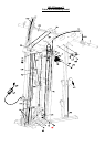
4. Now test movement of Weight Bar. Try lowering and raising the Weight Bar to the furthest points. If it sticks
or doesn’t work correctly, check the Weight Bar Cables over the pulleys to make sure they are not crossed
or twisted. According to Diagram 11 check for proper cable runs over pulleys and Cable Keepers are
installed, not over tightened. Make sure all wire harnesses are plugged together correctly.
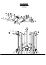
Step #5 WEIGHT STACK ASSEMBLY
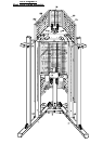
1. As shown in Diagram 4 assemble the two Upper Pulley Brackets (14) to the Guide Rod Top Plate (53) using
M10*20 Bolts (71) and M10 Washers (70). Tighten bolts securely.
2. To get started remove Weight Stack plates (65) and Top Plate (66) from its Cartons.
3. Now working on one side of unit at a time, insert Guide Rod Cups (53) into Base Rails (1 & 2) if not already
done. Next insert the Weight Stack Guide Rods (10) into each of the Guide Rod Cups.
4. Add Weight Plates (65) starting with the bottom #100 weight plate, slide down on Guide Rods. Keep Weight
Plates in order and facing to front of unit. Repeat until all weight plates are installed. This step is easier with
assistance from another person. Then install Top Plate (66).
5. Next install the Guide Rod Top Plate onto the Guide Rods (10) and bolt to Top Front Panel (15) using
M10*20 Bolts (71) and M10 Washers (70). Reference Diagram 4.
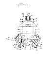
Step #6 CABLE INSTALLATION
There are three separate sets of cables for the resistance exercises. There are three different points to adjust
cables. 1. Weight Stack Adjuster Bolt 2. Large Equalizer Pulley Bracket
1. According to Diagram 5 install the Weight stack Cable (133). Found in Box 4. It runs thru the Weight Stack
Pulley Bracket, around the Equalizer Pulley Bracket (135) and then attaches to the to Top Rear Panel with
M10*40 Bolts (76) M10 Washers (70) M10 Nuts (82).
2. Next install the Lat Cable (134) Found in Box 2.
3. Next install the Cross Over Cable (132). Found in Box 4
7