


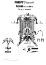
-- 5 --
Instructions for Assembly of the ProSpotfitness® HG-5 (con’t.)
Step #3 FINAL FRAME ASSEMBLY
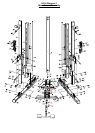
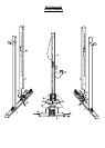
1. Now according to Diagram 3 install the Middle Cross Brace (18) using M10*65 Bolts (100), M10 Washers
(70 and M10 Nuts (82).
2. Next find the Front Top Rail (27) and attach the Front Panel Tabs (49) to the back of the Rail using Pan
Head Bolts M4*10 (118) & M4 Washers. Make sure the Tabs are facing downward.
3. Now install the Front Top Rail (27) using M12 x 105 Bolts (74), M12 Washers (20) and M12 Nuts (73).
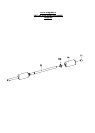
4. Now according to Diagram 1 attach the Cable Head assemblies (24) to each Front Upright Post (6) using
M12*70 Bolts, M12 Washers and M12 Nuts.
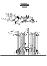
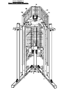
5. Installation of Weight Bar Cables (128 & 129): Uncoil the Cables coming out of the Locking Posts. Make
sure the Bar Cables are untwisted all the way down to the pulleys on the Locking Blocks (54, 55). Now feed
the Cables up and over the Small Double Groove Pulley (114). Then pull down the Rear Cable Knuckle and
attach to the Right and Left Base Rails (1, 2) using M12*100 Bolt (80), two Spacers (131), two M12 Washers
(72) and M12 Nuts (73) on each side. Make sure cables run outside the brace on the Locking Posts.
Reference Diagrams 7.
6. According to Diagrams 7 the rear cable knuckles part of the Weight Cables (128 & 129) when installed
should face towards the Locking Posts (7, 8). Now plug in the single plug of the Locking Post Wire Harness
(155) into the socket connection on the Rear Cable Knuckles on each side.
7. To finish the Weight Bar Cable installation take the Front Cable Knuckle that are hanging out of the top of
each post
and flip the cables forward toward the front of the unit between the Linking Plates over the double pulley just
installed.
8. Reference Diagrams 3, 7 & 11. The next step is to install the Double Groove Pulleys (112) with Right & Left
Weight Bar Support Brackets (32 & 33) in each Upper Linking Plate assembly towards the front of the unit
using M10*105 Bolts (103), M10 Washers (70) and M10 Nuts (82). Make sure the Weight Bar Cables (128 &
129) are untwisted all the way down into the Locking Post to the pulleys on the Locking Blocks (54 & 55).
Then lay the cables toward the front of the unit between the Linking Plates over the Double Pulley (112) to
be installed.
9. Now install the two Cable Keeper M6*90 Bolts (109), M6 Washers (110), M6 Lock nuts (111) in the Upper
Linking Plate assemblies above the two rear Double Groove Pulleys (114). These bolts prevent the Weight
Bar Cables from jumping off the pulleys during workout.
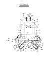
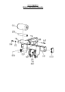
9. Next according to Diagram # 1 & 2, place the Electronic Box (101) on the Bottom Panel (4) so that the lights
are facing up and power plug of the Box receptacle is facing toward the back of the unit. Plug in Cross Brace
wire Harness (108) to each of side Electronic Box (101). Now place the Electronic Box Cover (56) over the
Electronic Box (101) and attach with two M10*95 Bolts (157), four M10 Washers (70) and two M10 locknuts
(82).
10. Now its time to tighten all the bolts previously installed. Starting at the bottom of the unit working your way to
the top, tighten bolts securely but do not over tighten.
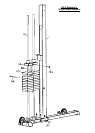
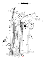
11. As shown in Diagram 2 feed the Power Supply Cord (102) thru the Rear Support Post into Electronic Box
(101). Next plug Power Adapter into Surge Protector Power Strip. Once it is plugged in the green light
should flash about once every second.
12. As shown in Diagram 2 feed the Neon power cord thru the Rear Support Post and connect to the Neon Light
wire harness. Then plug in the Neon Power Cord (155) into Neon Power supply (154). Next plug Neon
Power Cord (155) into a Surge Protector Power Strip. The Neon Light should turn on. If light does not turn
on, check wiring.