


-- 4 --
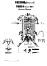
Instructions for Assembly of the ProSpotfitness® HG-5
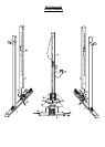
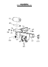
Step #1 MAIN FRAME ASSEMBLY
1. Referencing Diagrams 1 & 2, find the part Front Cross Brace (3). The Wire Harness (108) that runs thru this
part. This may be packed in this Cross Brace to prevent damage. Pull on ties and harnesses so that
connector ends hang loose out of access holes. Be careful not to pull too hard and remove or damage the
wire harnesses.
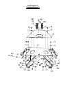
2. Now place the Rear Bottom Panel (5) in center of the assembly area. Next place the Right and Left Base
Rails (1, 2) opposite each other on each side of the Rear Bottom Panel. Note the 7/8” access holes for
wiring on side of Right and Left Base Rails (1, 2) should face inward. Now position the Front Plastic Bottom
Panel (4) (Remove paper cover on plastic) in front of the Rear Bottom Panel (5) between the Base Rails.
Insert Bolts (74) thru the Backing Plate (158) and attach the Side Rails (1 & 2) to the Rear Bottom Panel
using M12 x105 Bolts (74), M12 Washers (72) & M12 Nuts (73). Do not fully tighten bolts at this time.
3. Now place the Front Cross Brace (3) between rails so that the access holes with the harnesses hanging out
on the end of the Rear Cross Brace (3) align with the holes of the Base rails (1 & 2). Make sure the wire
harness that comes out of the middle of the Front Cross Brace (3) faces toward the back of the unit. Refer to
Diagrams 1 & 2.
4. Next feed the two Wire Harnesses (108) thru the access holes in the Right and Left Base Rails (1 & 2). Pull
up thru the round hole in the Right and Left Base Rails (1 & 2). Insert M12*105 Bolts (74) thru the Backing
Plate with Panel Hook (69) and attach the Side Rails (1 & 2) to the Front Cross Brace using M12 Washers
(72) & M12 Nuts (73). Do not fully tighten bolts at this time.
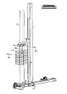
5. Now place the Right & Left Locking Posts on the Bottom Base Rails (1 &2) and secure with M10*20 Bolts
(71) and M10 Washers (70). Be careful not to crush wire harnesses at bottom of post. Then according to
Diagram 2 connect the two Wire Harnesses (108) to the Locking Post Wire Harnesses (107). Pull Barbell
Cables out of top of the Locking Posts and let Cable Knuckle and Barbell Cable hang towards the front of
the Locking Post for now.
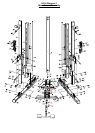
6. According to Diagram 1 place these Upright Posts (6) and place on the Bottom Base rails (1 & 2) and secure
with M10 *20 Bolts (71) and M10 Washers (70).
7. Before installing the Rear Upright Support Post (9), install the Neon Light (104 using M3*10 Screws (105)
and M3 Washers (106) according to Diagram 2.
8. Now place the Rear Upright Support Post (9) on the Rear Bottom Panel (5) and secure with M12* 20 Bolt
(75) and M12 Washer (72).
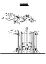
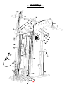
Step #2 MAIN UPPER FRAME ASSEMBLY
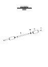
1. According to Diagram 4 attach Lat Pulley Bracket (17) to the Rear Top Panel (16) using M10*25 Bolts (88)
and M10 Washers (70). Tighten Bolts Securely.
2. Now according to Diagram 3 attach the Rear Top Panel to the Rear Upright Support Post (9) using M12*20
Bolt (75) and M12 Washer (72).
3. Now according to Diagram 3 install the Front Top Panel (15) to the Locking Posts (11) & (12) using M12*100
Bolts (80), M12 Washers (72) and M12 Nuts (73). Make sure the Barbell Cables are positioned in front of the
Bolts (80) just installed.
4. Now according to Diagram 3 install two Upper Linking Plates (26) on each side Front Upright Support Post
(6) using M12*100 Bolts (80), M12 Washers (72) and M12 Nuts (73).
5. Next attach the two Upper Linking Plates (26) to the Front top Panel (15) using M10*20 Bolts (71) and M12
Washers (70).
6. Now according to Diagram 3 install the four Small Double Groove Pulleys (114) in the two Upper Linking
Plates (26) in the using M10*100 Bolts (84), M10 Washers (70) and M10 Nuts (82).