


26
PROBLEM: The walking belt slows when walked on
S
OLUTION: a
. Use only a single-outlet surge suppressor that meets all of the specifications described on page 10.
b
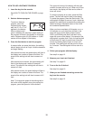
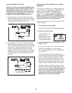
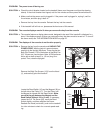
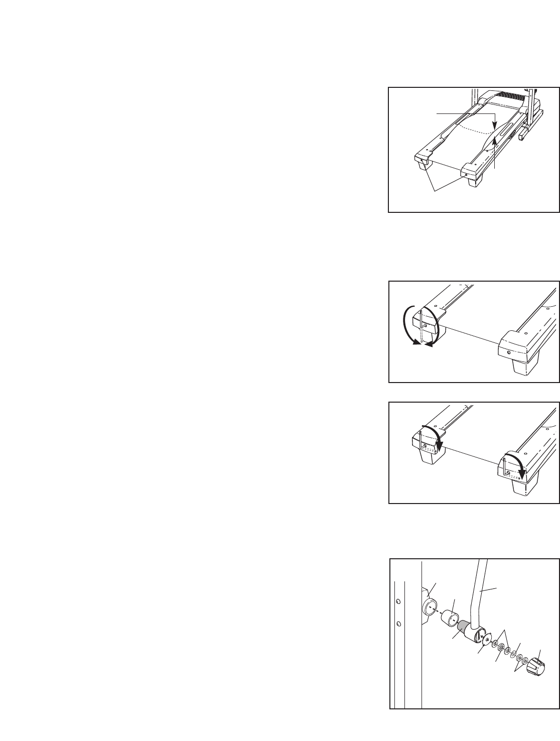
. If the walking belt is overtightened, treadmill perfor-
mance may decrease and the walking belt may be-
come damaged. Remove the key and
UNPLUG THE
POWER CORD. Using the hex key, turn both rear
roller bolts counterclockwise, 1/4 of a turn. When the
walking belt is properly tightened, you should be able
to lift each edge of the walking belt 2 to 3 in. (5 to 7
cm) off the walking platform. Be careful to keep the
walking belt centered. Then, plug in the power cord,
insert the key, and run the treadmill for a few minutes.
Repeat until the walking belt is properly tightened.
c. If the walking belt still slows when walked on, please see the front cover of this manual.
PROBLEM: The walking belt is off-center or slips when walked on
SOLUTION:
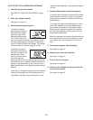
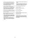
a. If the walking belt is off-center, remove the key and
UNPLUG THE POWER CORD. If the walking belt
has shifted to the left, use the hex key to turn the
left rear roller bolt clockwise 1/2 of a turn; if the walk-
ing belt has shifted to the right, turn the bolt coun-
terclockwise 1/2 of a turn. Be careful not to over-
tighten the walking belt. Then, plug in the power cord,
insert the key, and run the treadmill for a few minutes.
Repeat until the walking belt is centered.
b. If the walking belt slips when walked on, remove the
key and
UNPLUG THE POWER CORD. Using the
hex key, turn both rear roller bolts clockwise, 1/4 of a
turn. When the walking belt is correctly tightened, you
should be able to lift each edge of the walking belt 2
to 3 in. (5 to 7 cm) off the walking platform. Be careful
to keep the walking belt centered. Then, plug in the
power cord, insert the key, and carefully walk on the
treadmill for a few minutes. Repeat until the walking
belt is properly tightened.
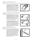
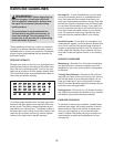
PROBLEM: The upper body arms squeak during use
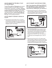
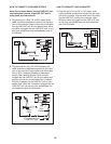
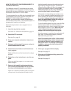
SOLUTION: a.
(Note: Correcting this problem requires a small amount
of white marine grease, available at hardware stores.)
Turn the Resistance Knob (A) counterclockwise and
remove it. Next, remove the Resistance Cone (B) and
the Upper Body Arm (24), along with the Resistance
Plate (C), Washers (D), Spring Washer (E), Thrust
Washers (F), and Thrust Bearing (G). (Note: If the
Resistance Sleeve [H] or the Resistance Plate [C]
comes out of the Resistance Bracket [I] or the
Resistance Cone [B], press it back in.) Apply a
thin
layer of white marine grease to the outer surface of
the Resistance Cone (B). Then, reattach all parts in
the order shown at the right.
Rear Roller Bolts
2–3 in.
b
a
b
H
I
24
A
F
E
C
G
a
D
B