


8
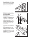
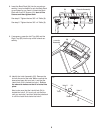
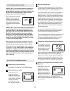
5. Hold a Bolt Spacer (3) inside the lower end of
t
he Right Upright (72). Insert a 3/8" x 4" Bolt (6)
with a 3/8" Star Washer (9) into the Right Upright
and the Bolt Spacer. Repeat this step with a sec-
ond Bolt Spacer (3), 3/8" x 4" Bolt (6), and 3/8"
S
tar Washer (9).
Orient the Right Upright (72) and the Right
Upright Spacer (74) as shown. Hold the Right
Upright Spacer and the Right Upright against the
Base (80).
Be careful not to pinch the Upright
Wire (78).
Finger tighten the two 3/8" x 4" Bolts
(6); do not fully tighten the Bolts yet.
Press a Base Endcap (75) into the Base (80).
74
78
72
9
75
3
6
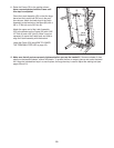
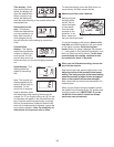
6.
Hold a Bolt Spacer (3) inside the lower end of
the Left Upright (71). Insert a 3/8" x 4" Bolt (6)
with a 3/8" Star Washer (9) into the Left Upright
and the Bolt Spacer. Repeat this step with a sec-
ond Bolt Spacer (3), 3/8" x 4" Bolt (6), and 3/8"
Star Washer (9).
Orient the Left Upright (71) and the Left Upright
Spacer (74) as shown. Hold the Left Upright
Spacer and the Left Upright against the Base
(80). Finger tighten the two 3/8" x 4" Bolts (6);
do not fully tighten the Bolts yet.
Press a Base Endcap (75) into Base (80).
73
71
6
80
3
75
9
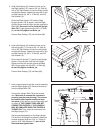
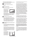
7.
Have a second person hold the console assembly
near the Right Upright (72). Remove the wire tie
from the Upright Wire (78).
Connect the Upright Wire (78) to the console
wire.
Make sure to connect the connectors
properly (see the inset drawing). The connec-
tors should slide together easily and snap
into place.
If they do not, turn one connector and
try again. IF THE CONNECTORS ARE NOT
CONNECTED PROPERLY, THE CONSOLE
MAY BE DAMAGED WHEN THE POWER IS
TURNED ON. Then, insert the connectors into
the Right Upright (72).
Set the console assembly on the Right Upright
(72) and the Left Upright (not shown). Attach the
console assembly with four 5/16" x 1" Bolts (5)
and four 5/16" Star Washers (7);
start all four
Bolts and then tighten them.
5
72
7
78
Console
Assembly
Console
Wire
Wire Tie
7
5
7
78
5
6
Rounded
Corner
80