6
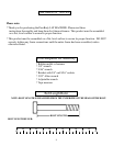
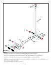
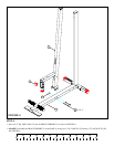
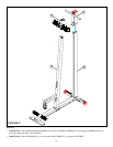
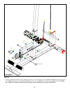
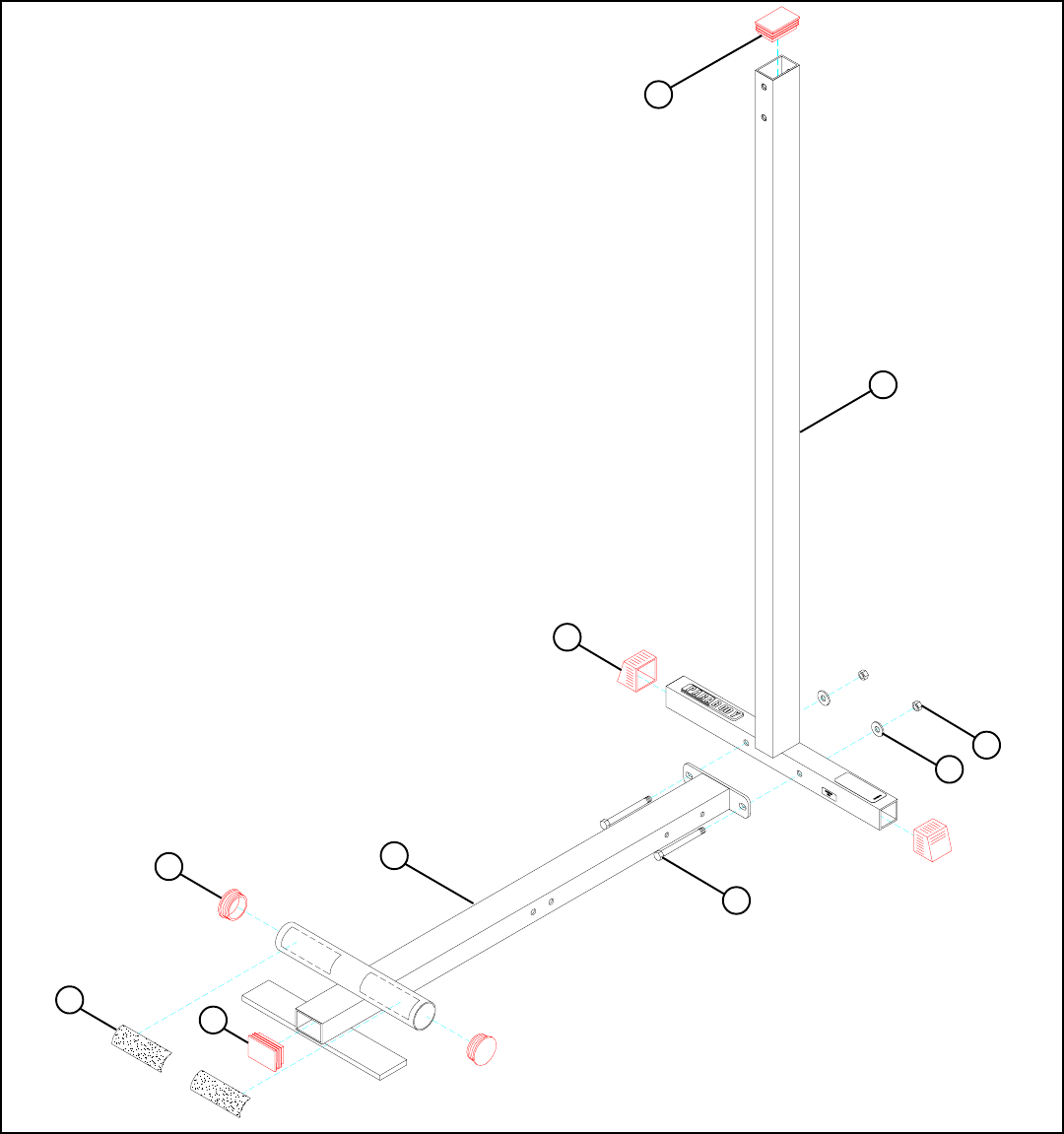
FIGURE 1
STEP 1:
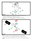
• Apply NON-SKID STRIPS (16) to BASE (1) as shown
• Attach two 2” SQ. COVER CAPS (18) onto the ends of the REAR UPRIGHT (3) as shown in FIGURE 1.
• Insert two 3 X 2” END CAPS (19) into the ends of the BASE (1) and REAR UPRIGHT (3) as shown in FIGURE 1.
• Insert two 2-1/2” ROUND END CAP (20) into the tube on the BASE FRAME (1) as shown in FIGURE 1.
32 1/2 X 3”
18
19
16
1
20
27
28
3
19
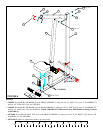
• LOOSELY assemble the REAR UPRIGHT (3) to the BASE (1) using two 1/2 X 3” BOLTS (32), two 1/2” WASHERS (27), and
two 1/2” LOCK NUTS (28). See FIGURE 1.


