


S]ep 1 5
A.
B.
@’~"-/2 X 3-1/2"
/p"~ H/-’-P ~’L"~
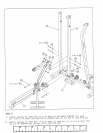
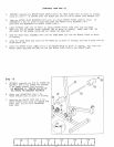
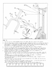
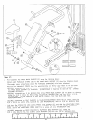
IMPORTANT
DO NOT OVERTIGHTEN 1 IN. NUTS,
//
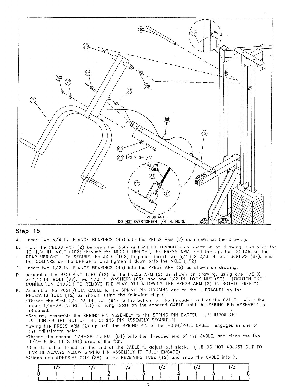
Insert two 3/4 IN. FLANGE BEARINGS (9.3) into the PRESS ARM (2) as shown on the drawing.
Hold the PRESS ARM (2) between the REAR and MIDDLE UPRIGHTS as shown in on drawling, and slide the
10-1/4 IN. AXLE (102) through the MIDDLE UPRIGHT, the PRESS ARM, and through the COLLAR on the
REAR UPRIGHT. To SECURE the AXLE (102) in place, insert two 5/16 X 3/8 IN. SET SCREWS (82),
the COLLARS on the UPRIGHTS and tighten if down onto the AXLE (102).
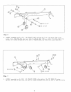
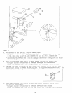
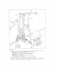
C. Insert two 1/2 IN. FLANGE BEARINGS (95) into the PRESS ARM (2) as shown on drawing.
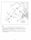
D.
Assemble the RECEIVING TUBE (12) fo the PRESS ARM.(2) as shown on drawing, using one 1/2
5-1/2 IN. BOLT (68), two 1/2 IN. WASHERS (65), and one 1/2 IN. LOCK NUT (90). (TIGHTEN
CONNECTION ENOUGH TO REMOVE THE PLAY, YET ALLOWING THE PRESS ARM (2) TO ROTATE FREELY)
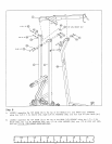
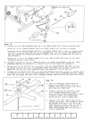
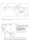
E. Assemble lhe PUSH/PULL CABLE fo the SPRING PIN HOUSING end fo the L-BRACKET on
RECEIVING TUBE (12) es shown, using ~he following steps:
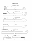
*Thread the first 1/4-28 IN. NUT (81) to the bottom of the threaded end of the CABLE. Allow the
other 1/4-28 IN. NUT (81) fo hang loose on the exposed CABLE until the SPRING PIN ASSEMBLY
attached.
*Securely assemble the SPRING PIN ASSEMBLY fo the SPRING PIN BARREL. (~ IMPORTANT
HI TIGHTEN THE NUT OF THE SPRING PIN ASSEMBLY SECURELY)
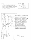
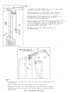
*Swing the PRESS ARM (2) up until the SPRING PIN of the PUSH/PULL CABLE engages in one
the adjustment holes.
~Thread the second 1/4-28 IN. NUT (81) onto the threaded end of ]he CABLE, and cinch the fwo
1/4-28 IN. NUTS (81).around the fla].
~Use the extra thread on Che end of ]he CABLE to adjust out slack. ( ~H DO NOT ADJUST OUT TO
FAR ~H ALWAYS ALLOW SPRING PIN ASSEMBLY TO FULLY ENGAGE)
~AHach one ADHESIVE CLIP (88) fo the RECEIVING TUBE (12) and snap ~he CABLE
0
I
1
I
2
I
~
I I , I I I I
, I I
i
, I I ! I I II I , I I I
17