


11
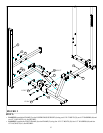
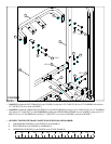
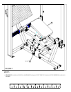
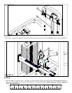
FIGURE 8
STEP 8:
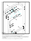
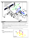
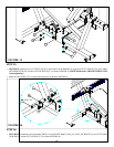
STEP 9:
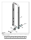
FIGURE 9
• Snap two WEIGHT PLATE BUSHINGS (27) into the
top of all twenty WEIGHT PLATES (29) as shown in
FIGURE 9.
27
29
30 3/8 X 1”
BUTTON
HEAD
34 3/8 X 3”
9
37
20
24
36
12
2
• SECURELY assemble the SEAT PAD (12) to the SEAT ADJUST (9) using two 3/8 X 3” BOLTS (34) and two 3/8” WASHERS (36). See
FIGURE 8.
• SECURELY assemble one SPRING PIN ASSEMBLY (24) to the spring pin barrel on the FRAME (2) as shown in FIGURE 8.
• Insert the PAD (12) & SEAT ADJUST (9) into the FRAME (2) while pulling back on the SPRING PIN ASSEMBLY (24) until it engages
in one of the adjustment holes. See FIGURE 8.
• SECURELY assemble one 3/8” X 1” BUTTON HEAD CAP SCREW (30) and one 3/8” LOCK NUT (37) to the last hole on the SEAT
ADJUST (9). See FIGURE 8.
• SECURELY insert one 3 X 2” SQ. END CAP (20) to the open end of the SEAT ADJUST (9). See FIGURE 8.