


9
Ocean Electric Winches 34 -
7
7
GB
2
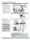
. Electrical wirin
g
installatio
n
3
2
1
5
4
S
ystem
V
o
l
tage
(
V
)
Di
stanc
e
Power suppl
y
to winc
h
C
ross
sect
i
ona
l
a
rea
C
able
si
ze
(
U
S
O
nly
)
B
attery s
i
z
e
1
2
U
p to 10 m (
33
ft) 5
0
mm
2
1/
Ø
Up to
3
00
A
mp/hr
s
1
2
10 to 15 m (
33
to 49 ft
)
70
mm
2
2/
Ø
1
2
15 to
20
m (4
9
to
66
f
t
)
9
5 mm
2
3/
Ø
2
4 Up to 7 m (2
3
ft
)
2
5 mm
2
3
2
4 7 to 10 m (2
3
to
33
ft)
35
mm
2
2
2
4 10 to 1
3
m (
33
to 4
3
ft
)
50
mm
2
1/
Ø
2
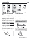
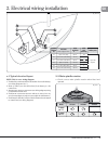
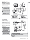
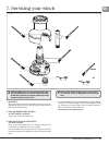
.1 Typical electrical layout
NOTE: This is not a wirin
g
dia
g
ram.
1. Position the recommended circuit breaker close to the batter
y
.
S
ee wirin
g
dia
g
rams Sec. 3.
2. Route 2 cables (see size table above) from batter
y
to the
co
n
t
r
ol
bo
x
.
3. Attac
h
motor ca
bl
es to contro
l
b
ox
(
see wiring
d
iagram
)
using
r
ecommen
d
e
d
ca
bl
e sizes.
4. Position t
h
e contro
l
b
ox near t
h
e winc
h
(
±1 metre
)
in a
d
ry
a
rea for watertig
h
t security an
d
accessi
bl
e for maintenance.
5.
P
os
i
t
i
o
n
dec
k
s
wi
tc
h
es
in vi
e
w
o
f win
c
h
.
R
oute
wir
e
a
n
d
attac
h
t
o control box (see wirin
g
dia
g
ram).
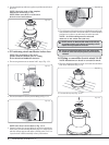
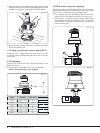
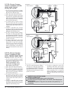
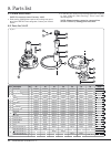
2.2 Main spindle rotation
• Check correct main s
p
indle rotation when fitted and
o
p
erated
.
Wi
nc
h
1
st
G
ear
2
nd
G
ear
3
rd
G
ear
2
S
peed
66
−77
3
S
peed
66
−77
Fi
g
. 2.1.1
Fig.
2
.
2
.1