11
Ocea
n E
lect
ri
c
Win
ches
3
4 -
77
GB
3
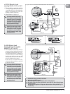
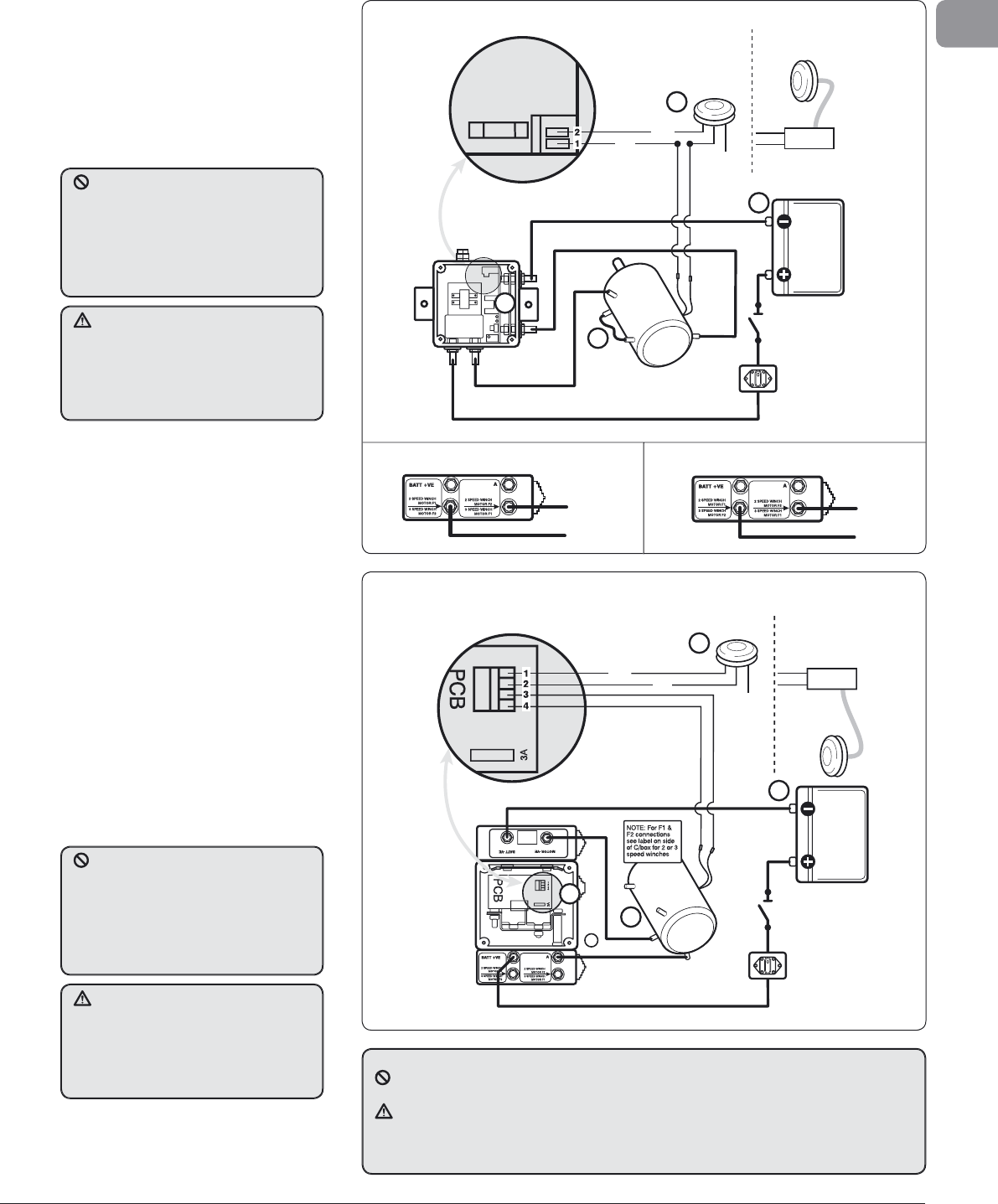
.3 ELS Electric Load
S
ensin
g
50-65, 12 V or 24 V
• This installation controls the winch b
y
L
ewmar’s uni
q
ue Overload Protection
C
ontrol Box (Fi
g
3.3.1), this allows the
w
inch to be o
p
erated u
p
to the Safe
W
orkin
g
Load for winch size.
• Ot
h
er features as Section 3.1
PCB
Thermal
Cutout
Isolator/Safety
Switch
Circuit
Breaker
Battery
A2
F1
Control Box
Battery +VE
Motor +VE
Grey
Not Used
Electric Switch Kit
69000016
1
Battery –VE
Motor –VE
A1
F2
2
4
Air Deck
Switch Kit
69000022
Sub Box
Black
Blue
3 A
Fuse
Two-way
Terminal Block
3
F
i
g
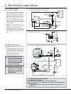
. 3.3.1 12 V or 24 V Control box with overload
p
rotection. Also see Section 3.7.
3.
4 EL
S
Electric Loa
d
S
ensing 2/3 speed controlle
r
66
/
68
-77
,
12
V or
2
4
V
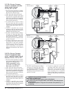
• This installation controls the winch b
y
L
ewmar’s uni
q
ue Overload Protection
&
Autoshift Control Box (Fi
g
. 3.4.1).
T
hi
s
a
ll
o
w
s
t
h
e
win
c
h
to
be
sta
r
ted
in
1
st an
d
if reac
h
es t
h
e Safe Wor
k
ing
L
oa
d
, for t
h
e winc
h
size an
d
gear, wi
ll
a
utomatica
ll
y s
h
ift t
h
e winc
h
into 2n
d
g
ear for comp
l
ete
l
oa
d
contro
l
.
In t
h
e case of a 3 spee
d
winc
h
(
Fig.
3
.4.1
b)
t
h
e switc
h
must
b
e re-se
l
ecte
d
t
o achieve 3rd
g
ear.
F
ig. 3.4.1a 2
S
peed winch electrical connection
s
Blue
Black
Grey
Not Used
Electric Switch Kit
69000016
2
Air Deck
Switch Kit
69000022
Sub Box
Isolator/Safety
Switch
Circuit
Breaker
Battery
F1
Control Box
Battery +VE
Motor – VE
1
Battery –VE
Motor –VE
A2
A1
F2
3
4
Thermal
Cutout
8
F
i
g
. 3.4.1 2/3 S
p
eed 12 V or 24 V control box with overload
p
rotection. Also see Section 3.7
.
F
i
g
. 3.4.1b 3 S
p
eed winch electrical connections
C
onnect the power supply cables
to the batter
y
last when the winch
i
nstallation has been com
p
leted
a
n
d
c
h
ec
k
ed
f
o
r
co
rr
ec
t in
s
t
a
ll
a
ti
o
n.
In
co
rr
ec
t
co
nn
ec
ti
o
n
o
f m
o
t
o
r
cab
l
es
m
ay dama
g
e the unit
.
Total volta
g
e dro
p
MUST NOT exceed
5
% of su
pp
ly over com
p
leted cablin
g
i
nstallation.
C
heck all connections
f
or water tight security. Lewmar
r
ecommends an isolator to be
fi
tted in
t
h
e c
i
rcu
i
t
i
n an access
ibl
e pos
i
t
i
on as
close as
p
ossible to the su
pp
ly
.
C
onnect the power supply cables
to t
h
e
b
attery
l
ast w
h
en t
h
e w
i
nc
h
i
nstallation has been com
p
leted
a
n
d
c
h
ec
k
ed
f
o
r
co
rr
ec
t in
s
t
a
ll
a
ti
o
n.
In
co
rr
ec
t
co
nn
ec
ti
o
n
o
f m
o
t
o
r
cab
l
es
m
ay dama
g
e the unit
.
Total volta
g
e dro
p
MUST NOT exceed
5
% of su
pp
ly over com
p
leted cablin
g
i
nstallation.
C
heck all connections
f
or water tight security. Lewmar
r
ecommends an isolator to be
fi
tted in
t
h
e c
i
rcu
i
t
i
n an access
ibl
e pos
i
t
i
on as
c
l
ose as poss
ibl
e to t
h
e supp
l
y
.
N
U
MBER KEY F
O
R ALL ELE
C
TRI
C
AL DIA
G
RAM
S
n
Ne
g
ative earth MUST be used
.
o
The deck switch wires MU
S
T be fi tted as shown on wiring diagrams
.
p
C
onnect all low power wiring
(
deck switches, motor cutout etc.
)
before fi tting high power
ca
bl
es to contro
ll
er
.
q
C
able boots are supplied for all high power cable connections, follow guidelines Fig. 2.1.1
f
or cable sizin
g.
F1
F2
F2
F1


