


12
O
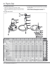
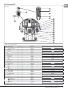
cean Electric Winches 34 - 7
7
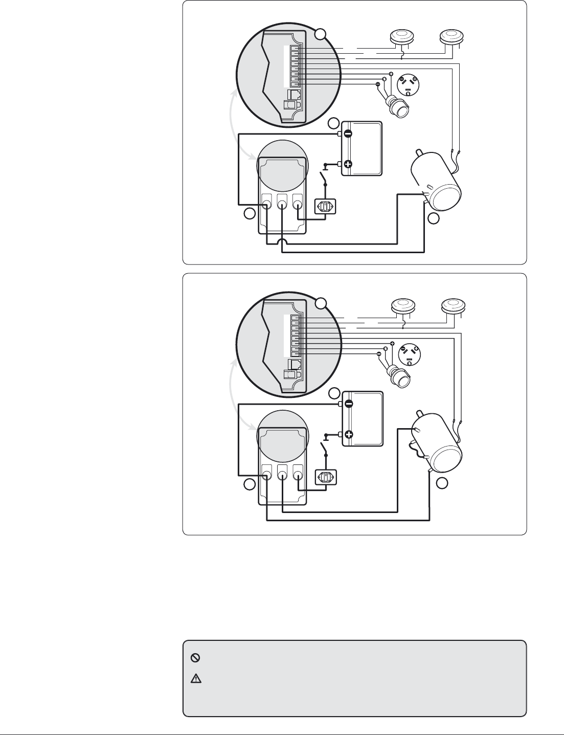
12345678
Black
Black
Grey
Not Used
SW 1
Electric Switch Kit
69000018
3
Grey
Not Used
SW 2
Electric Switch Kit
69000018
Blue
1
2
4
Thermal
Cutout
Isolator/Safety
Switch
Circuit
Breaker
Battery
EVC
Control Box
Battery +VE
Motor – VE
Battery –VE
Motor +VE
D1
D2
(Optional)
Vario Control
Two-way
Terminal Block
3 Amp
Fuse
BAT+
MOT+
BAT–
MOT–
A2
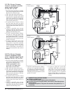
Fi
g
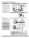
. 3.5.1
A
lso see
S
ection 3.7.
3.5 EV
C
E
l
ectr
i
c Var
i
a
bl
e
Control.
S
tandard controller
si
ng
l
e spee
d
w
i
nc
h
es
34-48, 12 V
&
24 V
• T
h
e EVC winc
h
contro
ll
er is a varia
bl
e
spee
d
motor contro
ll
er w
h
ic
h
can
d
rive
t
h
e winc
h
in 3
d
ifferent ways:
1. SW 1 drives the winch at full speed.
2. SW 2 drives the winch at a set speed
determined b
y
ad
j
ustable dial marked
(SP) on the control box. On suppl
y
the
dial is preset b
y
Lewmar to drive the
winc
h
at 60% of fu
ll
s
p
ee
d
.
3. If optiona
l
Vario Contro
l
is fitte
d
t
h
en t
h
e winc
h
wi
ll
d
rive at a spee
d
d
etermine
d
b
y a
d
justment of t
h
e Vario
Contro
l
w
h
en
d
ec
k
switc
h
(
SW 2
)
is
engage
d.
• Th
e
EV
C
co
n
t
r
o
ll
e
r
uses
cu
rr
e
n
t
sensin
g
to halt the o
p
eration of the
win
c
h wh
e
n
t
h
e
win
c
h h
as
r
eac
h
ed
i
ts
Maximum Safe Workin
g
Load.
• The EVC controller features a Ram
p
/
Soft Start to contro
l
t
h
e winc
h
start
up, a
d
justment of
d
ia
l
RA wi
ll
vary t
h
e
start perio
d
b
etween 0.5 - 5 secon
d
s.
T
h
e
d
ia
l
is preset
b
y Lewmar for a start
p
eriod of 1 second.
• In order to ad
j
ust the speed (SP)
and Ram
p
(RA) dials, unscrew the
p
lu
g
screws, on to
p
of the controller
4 full turns and retract the
p
lu
g
/
screw assem
bl
y. Use an e
l
ectrica
l
s
l
otte
d
(
2.5mm Max.
)
screw
d
river to
a
d
just t
h
e interna
l
d
ia
l
to t
h
e
d
esire
d
sett
i
ng
.
3
.
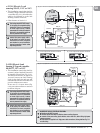
6 EV
C
E
l
ectr
i
c Var
i
a
bl
e
Control. Standard & high
power controller sin
g
le speed
w
i
nc
h
es 50-65
,
12 V
&
24
V
• Th
e
EV
C
win
c
h
co
n
t
r
o
ll
e
r i
s
a
v
a
ri
ab
l
e
s
p
eed motor controller which can drive
t
h
e winc
h
in 3
d
ifferent ways:
NOTE:
S
tandard EVC used
on 50−65 24 V. H
i
g
h
powe
r
EV
C
use
d
on 50−65 12 V
.
1. SW 1
d
rives t
h
e winc
h
at fu
ll
spee
d
.
2. SW 2
d
rives t
h
e winc
h
at a set spee
d
determined b
y
ad
j
ustable dial marked
(SP) on the control box. On suppl
y
the
dial is preset b
y
Lewmar to drive the
winch at 60% of full s
p
eed.
3. If o
p
tional Vario Control is fitted
t
h
en t
h
e winc
h
wi
ll
d
rive at a spee
d
d
etermine
d
b
y a
d
justment of t
h
e Vario
Contro
l
w
h
en
d
ec
k
switc
h
(
SW 2
)
is
engage
d.
• Th
e
EV
C
co
n
t
r
o
ll
e
r
uses
cu
rr
e
n
t
sensin
g
to halt the o
p
eration of the
win
c
h wh
e
n
t
h
e
win
c
h h
as
r
eac
h
ed
i
ts
Maximum Safe Workin
g
Load.
12345678
Black
Black
Grey
Not Used
SW 1
Electric Switch Kit
69000018
3
Grey
Not Used
SW 2
Electric Switch Kit
69000018
Blue
1
2
4
Isolator/Safety
Switch
Circuit
Breaker
Battery
EVC
Control Box
Battery +VE
Motor – VE
Battery –VE
Motor +VE
(Optional)
Vario Control
Two-way
Terminal Block
3 Amp
Fuse
BAT+
MOT+
BAT–
MOT–
Thermal
Cutout
F1
A2
A1
F2
Fi
g
. 3.6.1
A
lso see
S
ection 3.7.
• The EVC controller features a Ram
p
/
So
f
t
Sta
r
t
to
co
n
t
r
o
l
t
h
e
win
c
h
sta
r
t
up, ad
j
ustment of dial RA will var
y
the
start
p
eriod between 0.5 - 5 seconds.
T
h
e
d
ia
l
is preset
b
y Lewmar for a start
perio
d
of 1 secon
d
.
• In order to ad
j
ust the speed (SP)
and Ram
p
(RA) dials, unscrew the
p
lu
g
screws, on to
p
of the controller
4 full turns and retract the
p
lu
g
/
screw assem
bl
y. Use an e
l
ectrica
l
s
l
otte
d
(
2.5mm Max.
)
screw
d
river to
a
d
just t
h
e interna
l
d
ia
l
to t
h
e
d
esire
d
sett
i
ng
.
N
U
MBER KEY F
O
R ALL ELE
C
TRI
C
AL DIA
G
RAM
S
n
Ne
g
ative earth MUST be used
.
o
The deck switch wires MU
S
T be fi tted as shown on wiring diagrams
.
p
C
onnect all low power wiring
(
deck switches, motor cutout etc.
)
before fi tting high power
ca
bl
es to contro
ll
er
.
q
C
able boots are supplied for all high power cable connections, follow guidelines Fig. 2.1.1
f
or cable sizin
g.