5
Ocean Electric Winches 34 -
7
7
GB
1
. Installatio
n
Always kee
p
in mind the s
p
ace available below the deck for the
motor
g
earbox.
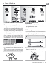
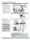
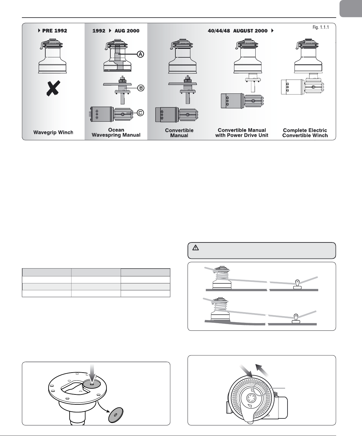
PRE 1992
1992
AUG 2000 40/44/48 AUGUST 2000
Wavegrip Winch
Ocean
Wavespring Manual
Convertible
Manual
Convertible Manual
with Power Drive Unit
Complete Electric
Convertible Winch
A
1
.2 Prepar
i
n
g
t
h
e manua
l
w
i
nc
h
f
or convers
i
on to e
l
ectr
i
c
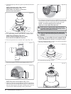
• Remove t
h
e winc
h
from t
h
e
d
ec
k
(
if a
l
rea
d
y insta
ll
e
d)
an
d
r
emove t
h
e Centre P
l
ate, w
h
ic
h
is
l
ocate
d
on t
h
e un
d
ersi
d
e
o
f t
h
e Centre Stem,
b
y using a soft
h
ammer an
d
punc
h
(
Fig.
1
.2.1
)
.
• Remove an
y
sharp edges and clean, to remove all old bedding
/
s
ealin
g
com
p
ounds from the underside of the Centre Stem.
1
.1 I
d
ent
if
y
i
ng t
h
e manua
l
convert
ibl
e w
i
nc
h
• Fi
g
. 1.1.1
Pre
O
cean w
i
nc
h
es,
i
.e.
fi
xe
d
j
aw Wave
G
r
i
p
wi
nc
h
es, ma
d
e
b
e
f
ore 1992 are N
O
T convert
ibl
e.
Converti
bl
e manua
l
winc
h
es ma
d
e in August 2000 wi
ll
b
e
d
ate
m
ar
k
e
d
H
/
00 on t
h
e centre stem,
(
H = August; 00 = year 2000
)
.
Th
ey a
l
so carry a
bl
ue stic
k
er on t
h
e screw-on top-cap s
h
owing
a
winc
h
h
an
dl
e an
d
a
h
an
d
operating an e
l
ectric
d
ec
k
switc
h
.
T
hese winches can be converted b
y
adding the Power Drive
B
ase (B) unit and the re
q
uired Motor Gearbox (C), Control
B
ox and Switch-
g
ear (12 V or 24 V).
• Ocean Wave S
p
rin
g
manual winches made between 1992 and
A
ugust 2000 are NOT fi tte
d
wit
h
t
h
e necessary centre stem
t
o convert to powere
d
operation. A Centre Stem Kit
(
A
)
is
a
vai
l
a
bl
e to convert t
h
e ear
l
y Ocean Wave Spring winc
h
es
f
rom
(
1992 to Ju
l
y 2000
)
. T
h
e part num
b
ers are
l
iste
d
b
e
l
ow.
P
re Ocean Winches, i.e. fi xed
j
aw Wave Grip winches, made
be
f
o
r
e
1
99
2
a
r
e
N
O
T
co
nv
e
r
t
i
b
l
e.
Win
c
h M
odel
Descri
p
tio
n
P
a
rt N
u
m
be
r
40
C
entre
S
tem Ki
t
480
4
003
7
44
C
entre Stem Ki
t
4
8044037
48
C
entre
S
tem Ki
t
4
80480
3
7
F
ig. 1.
2
.
1
1.3 F
i
tt
i
ng a comp
l
ete e
l
ectr
i
c
win
c
h fr
o
m n
ew
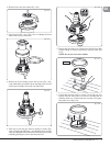
• Test fi t t
h
e winc
h
to t
h
e Power Drive Base an
d
Gear
b
ox to
c
h
ec
k
t
h
e orientation an
d
t
h
e necessary c
l
earence nee
d
e
d
BEF
O
RE DRILLIN
G
ANY H
O
LE
S.
• N
o
w f
o
ll
o
w
sect
i
o
n
s
1
.
4
a
n
d
1
.5.
1.4 Pos
i
t
i
on
i
ng w
i
nc
h
a
b
ove
d
ec
k
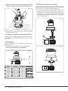
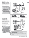
• Lewmar recommend that the ro
p
e enters onto the drum at an
ang
l
e of –5° to –10° to t
h
e
b
ase axis of t
h
e winc
h
. To ac
h
ieve
t
h
is ang
l
e it may
b
e necessary to use a
b
ase we
d
ge w
h
en
insta
ll
ing t
h
e winc
h
(
Fig. 1.4.1
)
. T
h
e winc
h
must
b
e mounte
d
on an even sur
f
ace.
-5° to -10°
-5° to -10°
LOAD
OUTPUT GEAR
2 SPEED / 3 SPEED WINCHES
LINE ENTRY
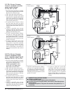
• If practica
l
, for
b
est performance, t
h
e winc
h
s
h
ou
ld
b
e insta
ll
e
d
so t
h
at t
h
e output gear is situate
d
in t
h
e optimum position in
re
l
ation to t
h
e
l
oa
d
(
Fig. 1.4.2
)
.
Fi
g
.
1
.4.
1
Fig. 1.4.
2


