


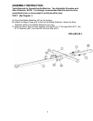
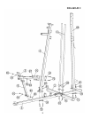
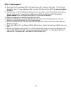
STEP 2 (See Diagram 2)
A.) Insert the two Guide Rods (#11) into the holes on the Middle Stabilizer (#2).
Secure each Guide Rod with one M10 x 1” Allen Bolt (#81) and two ¾” Washers
(#91) from the bottom. Slide two Ø 2 ¼” x 1” Guide Rod Rubber Bumpers (#39)
onto the two Guide Rods from top to bottom.
B.) Do not tighten all Nuts and Bolts starting from this procedure until instructed
to do so.
C.) Attach the Power Station Vertical Frame (#26) to the Rear Stabilizer (#20). Secure
them with two M10 x 2 3/8” Carriage Bolts (#72), one 4 ¾” x 3 ½” Bracket (#18),
two Ø ¾” Washers (#91), and two M10 Aircraft Nuts (#97).
D.) Attach the Vertical Frame (#4) onto the Base Frame (#3). Secure them with two
M10 x 2 3/8” Carriage Bolts (#72), one 4 ¾” x 3 ½” Bracket (#18), two Ø ¾”
Washers (#91), and two M10 Aircraft Nuts (#97).
E.) Attach the Vertical Seat Support (#5) to the Base Frame. Secure it with two M10 x
1” Allen Bolts (#81) and two Ø ¾” Washers (#91).
F.) Attach the Seat Support (#6) to the Vertical Frame. Secure it with two M10 x 2 3/8”
Carriage Bolts (#72), one 4 ¾” x 3 ½” Bracket (#18), two Ø ¾” Washers (#91), and
two M10 Aircraft Nuts (#97).
G.) Attach the Seat Support to the Vertical Seat Support. Secure it with M10 x 1” Allen
Bolts (#81) and two Ø ¾” Washers (#91).
8