


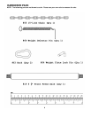
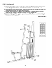
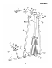
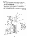
STEP 4 (See Diagram 4)
A.) Place the Upper Frame (#1) onto the Vertical Frame (#4).
B.) Attach the brackets on the Upper Frame to the two Guide Rods. Secure the Guide Rods to
the brackets with two M10 x 1” Allen Bolts (#81) and Ø ¾” Washers (#91).
C.) Secure the Upper Frame to the Power Station Vertical Frame (#26) with two M10 x 2 3/8”
Carriage Bolts (#72), one 4 ¾” x 3 ½” Bracket (#18), two Ø ¾” Washers (#91), and two M10
Aircraft Nuts (#97).
D.) Secure the Upper Frame to the Vertical Frame with two M10 x 2 3/8” Carriage Bolts (#72),
one 4 ¾” x 3 ½” Bracket (#18), two Ø ¾” Washers (#91), and two M10 Aircraft Nuts (#97).
E.) Securely tighten all Nuts and Bolts previously installed in Step-2 and Step-4.
F.) Attach the Leg Developer (#7) to the open bracket on Seat Support (#5). Secure it with one
M12 x 3 1/8” Allen Bolt (#77), two 1” Washers (#92), and one M10 Aircraft Nut (#98).
11