


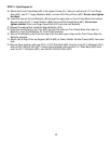
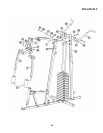
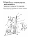
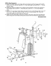
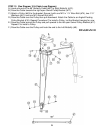
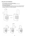
STEP 11 (See Diagram 11 & Cable Loop Diagram)
A.) Attach the 159” Lower Cable (#58) to the opening bracket on Leg Developer (#7).
B.) Attach a Pulley (#40) to the opening. Secure it with one M10 x 2 ½” Allen Bolt
(#76), two 1” x 5/8” Pulley Bushings (#52), and one M10 Aircraft Nut (#97).
C.) Draw the Cable underneath the Pulley to the opening on Vertical Seat Support
(#6). Repeat B to install a Pulley.
D.) Draw the Cable underneath the Pulley through the opening on bottom of Vertical
Frame (#4), to the open bracket on Base Frame (#3).
E.) Attach a Pulley to the bracket. Secure it with one M10 x 1 ¾” Allen Bolt (#74),
two Ø ¾” Washers (#91), and one M10 Aircraft Nut (#97).
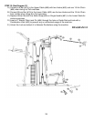
F.) Draw the Cable around the Pulley then upward to the Angled Floating Pulley
Bracket (#16) installed in Step-10. Repeat E to install a Pulley.
G.) Draw the Cable around the Pulley then downward to an open bracket on Base
Frame. Repeat E to install a Pulley.
H.) Draw the Cable around the Pulley and pull the Cable upward to the Double
Floating Pulley Brackets (#16) previously installed in Step-9.
I.) Attach a Pulley to selected holes. Secure the Pulley with one M10 x 2” Allen Bolt
(#75), two Ø ¾” Washers (#91), two Cable Retainer (#99), and one M10 Aircraft
Nut (#97).
J.) Draw the Cable around the Pulley and downward to the open bracket on Base
Frame. Secure the end of Cable to the bracket with one M10 x 1’ Allen Bolt
(#81), two Ø ¾” Washers (#91), and one M10 Aircraft Nut (#97).
K.) If the whole Cable system is too loose, adjust the tension of the cable system by
moving up or down the lower pulley on the Double Floating Pulley Bracket.
Moving up the pulley up will increase the tension in the pulley system;
conversely, lowering the pulley will decrease the tension.
22