


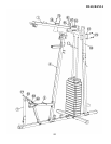
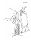
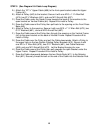
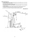
STEP 9 (See Diagram 9 & Cable Loop Diagram)
A.) Attach the 127 ½” Upper Cable (#56) to the front open bracket under the Upper
Frame (#1).
B.) Attach a Pulley (#40) to the bracket. Secure it with one M10 x 1 ¾” Allen Bolt
(#74), two Ø ¾” Washers (#91), and one M10 Aircraft Nut (#97).
C.) Draw the Cable under the Upper Frame towards the back of the machine to the
open bracket on Vertical Frame (#4). Repeat B to install a Pulley.
D.) Draw the Cable around the Pulley then pull back to the opening on the Front Press
Base (#8).
E.) Attach a Pulley to the opening. Secure it with one M10 x 7 ½” Allen Bolt (#73), two
Ø ¾” Washers (#91), and one M10 Aircraft Nut (#97).
F.) Draw the Cable around the Pulley then through the opening on the Vertical Frame
(#4) to the open bracket on the back of Vertical Frame. Repeat Procedure B to
install a Pulley.
G.) Draw the Cable over the Pulley and pull the Cable downwards. Attach a Pulley to
the upper hole on the two Double Floating Pulley Brackets (#13). Secure it with
one M10 x 2” Allen Bolt (#75), two Ø ¾” Washers (#91), two Cable Retainers
(#99), and one M10 Aircraft Nut (#70). Let the Bracket hanging for now.
H.) Draw the Cable around the Pulley then pull upwards the open bracket under the
Upper Frame. Repeat Procedure B to install a Pulley.
I.) Draw the Cable downwards between the two Guide Rods (#11) to the Selector
Rod (#21). Securely thread the bolt on the end of the Cable into the Selector Rod.
19