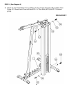
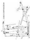
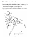
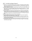
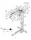
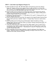
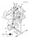
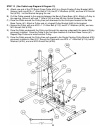
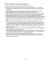
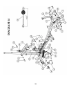
STEP 14 (See Cable Loop Diagram & Diagram 14)
A.) Attach the 163” Lower Cable (#53) to the Swivel Frame (#11).
B.) Install a Pulley to the bracket on the Swivel Frame with one M10 x 1 ¾” Allen Bolt
(#113), two Ø ¾” Washers (#124), one L-shaped Bracket (#46) and one M10 Aircraft
Nut (#128).
C.) Draw the Cable around the Pulley then pull upward to the Double Floating Pulley
Bracket (#36) previously installed in Step12-E. Install another Pulley.
D.) Draw the Cable around the Pulley then pull downward to the first open bracket on the
left. Repeat the Step B above to install a Pulley with a U-shaped Pulley Bracket (#47).
E.) Draw the Cable around the Pulley then pull upward to the Single Floating Pulley
Bracket (#35) previously installed in Step 13-A. Repeat Step B above to install a Pulley.
F.) Draw the Cable around the Pulley then pull downward to the open bracket on the Main
Base Frame. Repeat Step B above to install a Pulley with a L-shaped Pulley Bracket
(#46).
G.) Draw the Cable underneath the three Pulleys previously installed in Step 13 and
through the opening on the bottom of the Front Vertical Beam (#7). Continuously draw
the Cable underneath the Small Pulley Wheel (#65) on the Main Base Frame to the
opening on the Front Support Frame (#3). Attach a Pulley to the opening. Secure it with
one M10 x 2 ½” Allen Bolt (#117), two Ø 7/8” Pulley Bushings (#70), and one M10
Aircraft Nut (#128).
H.) Draw the Cable over the Pulley and to the open bracket on the Main Seat Support (#2).
Repeat Step B above to install a Pulley.
I.) Draw the Cable through the opening on the Main Seat Support to the open bracket on
the Leg Developer (#26). Secure the end of Cable with one M10 x 1” Allen Bolt (#114),
two Ø ¾” Washers (#124), and one M10 Aircraft Nut (#128).
J.) Use a C-clip (#136) to connect a Long Chain (#135) to the end of the Cable. Use
another C-clip to connect the Shiver Bar (#24), Single Handle (#61), or Ankle Strap
(#60) for various exercises.
23


