


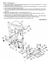
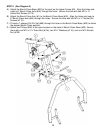
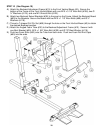
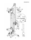

STEP 10 (See Diagram 10)
A.) Attach the Backrest Adjustment Frame (#10) to the Front Vertical Beam (#3). Secure the
bottom of the Frame to the Front Vertical Beam with one M10 x 3 1/8” Allen Bolt (#106), two Ø
¾” Washers (#118), and one M10 Aircraft Nut (#125).
B.) Attach two Backrest Swivel Brackets (#38) to the pivot on the Frame. Attach the Backrest Board
(#60) to the Brackets. Secure the Board with two M10 x 1 1/8” Allen Bolts (#99) and Ø ¾”
Washers (#118).
C.) Thread a T-shaped Pull Pin Set (#69) through the hole on the Front Vertical Beam (#3) to obtain
the desired Backrest position.
D.) Attach the Angled Foam Tube (#30) to the Backrest Adjustment Frame (#10). Secure it with
one Bent Bracket (#29), M10 x 1 5/8” Allen Bolt (#100) and Ø 7/8” Bent Washer (#119).
E.) Push two Foam Rolls (#62) onto the Tube from both ends. Push two Foam Roll End Caps
(#90) into the ends.
16