8
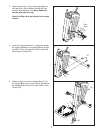
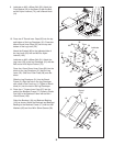
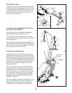
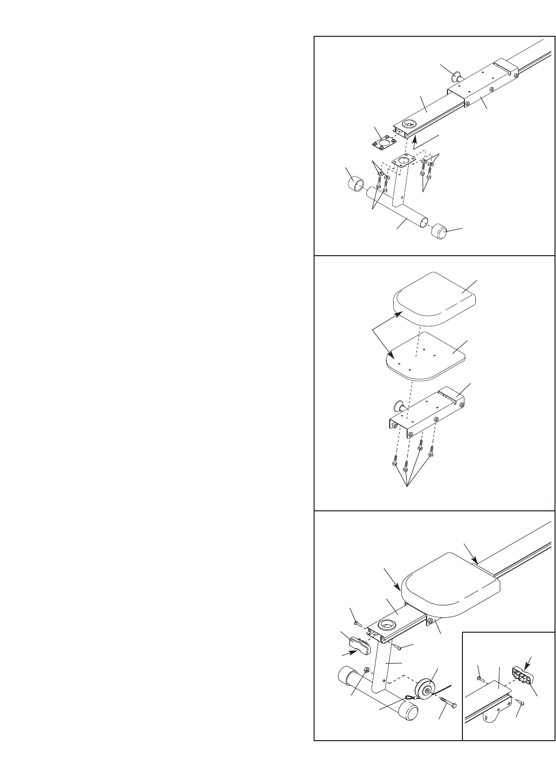
6. Press two 57.1mm Round Outer Caps (59) onto
the ends of the Front Leg (1).
Pull the Seat Knob (36) out as far as it will go and
r
emove the Seat Frame (19) from the Bench
Frame (2) and set it aside.
Orient the Bench Frame (2) as shown. Slide the
Front Bench Frame Plate (39) into the indicated
end of the Bench Frame, and align the holes in
the Plate with the holes in the Bench Frame.
Orient the Front Leg (1) as shown. Attach the
Front Leg to the Bench Frame (2) with the Front
Bench Frame Plate (39), four M8 x 25mm Button
Screws (74) and four M8 Split Washers (104).
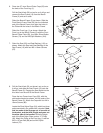
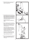
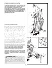
7. Orient the Seat (20) and Seat Backing (115) as
shown. Attach the Seat and Seat Backing to the
Seat Frame (19) with four M6 x 16mm Screws
(67).
8. Pull the Seat Knob (36, not shown) out as far as
it will go, and slide the Seat Frame (19) onto the
Bench Frame (2). Engage the Seat Knob into the
third hole from the end of the Bench Frame.
Press the two Frame Inner Caps (58), with the
wide ends oriented as shown, into the ends of the
Bench Frame (2). Attach the Caps with four M4 x
16mm Screws (86).
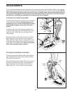
Locate the Short Nylon Rope (54), which has three
ends connected in the middle with a bracket. Note
that two ends of the Rope go out of one side of
the bracket, and the third (single) end goes out
the other side of the bracket. Route the single
end of the Short Nylon Rope under a “V”-Pulley
(49). Attach the Pulley to the Front Leg (1) with an
M10 x 107mm Bolt (88) and an M10 Nylon
Locknut (72).
6
7
8
2
39
Holes
1
9
36
1
74
104
104
74
59
59
20
115
Round
End
Third
Hole
19
67
58
Wide
End
W
ide
End
86
36
86
86
86
58
19
88
49
72
54
1
2
2


