


14
C
D
B
A
42
10
106
82
110
110
11
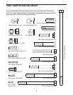
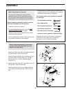
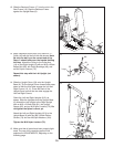
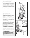
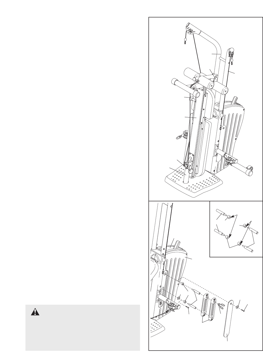
ATTACHING EXTERIOR BANDS
Remove the 1/2” x 1” Button Screw (110) with the 1/2”
Small Washer (82) from each side of the resistance
system. Remove the Side Covers (42) from the Left
and Right Covers (10, 11). Remove the 1/2” x 1”
Button Screw with the 1/2” Washer (106) from each
side of the resistance system.
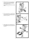
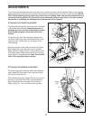
Slide the four 17.5mm Spacers (A) onto the four
Resistance Rods (B). (See the inset drawing for cor-
rect orientation.) Slide the two removed 1/2” Washers
(106) onto two of the Rods.
Attach a Resistance Rod (B) and a Resistance Rod
with a 1/2” Washer (106) to the indicated locations on
the resistance system. Attach the other two Resistance
Rods to the other side of the resistance system.
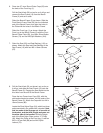
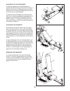
Slide an Exterior Band (C) onto each set of Resistance
Rods (B). For more resistance, add a second Band to
each set of Rods.
Note: It may be necessary to
stretch the Bands to slide them onto the Rods.
Secure the Exterior Bands with the two Clips (D).
T
o purchase a
MAX
P
ACK,
call our Customer Service
Department at the number listed on the front cover of
this manual.
The
MAX PACK shown is model number
GGMC0921.
36
21
9
8
2
41
4
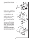
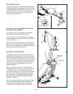
STORING THE RESISTANCE SYSTEM
T
o store the resistance system, secure the Seat Knob
(36) into the adjustment hole in the Bench Frame (2)
t
hat is closest to the Leg Developer (21) (see
ADJUSTING THE BACKREST on page 12). Remove
the indicated Bench Knob (41) from the Base (4) and
lift the Leg Developer so that it rests against the Left
and Right Uprights (8, 9). Engage the Knob into the
indicated hole in the Base.
IMPORTANT:Always place the
same number of Exterior Bands (C) on each
side of the resistance system. Use only the
Bands included with a GOLD’S GYM
MAX
PACK. Always secure the Bands with the Clips
(D).
Small
Hole
Large
Hole
A
A
B
B
A